- Home
- Product Categories
- Distance
- PIR Motion Sensor (JST)

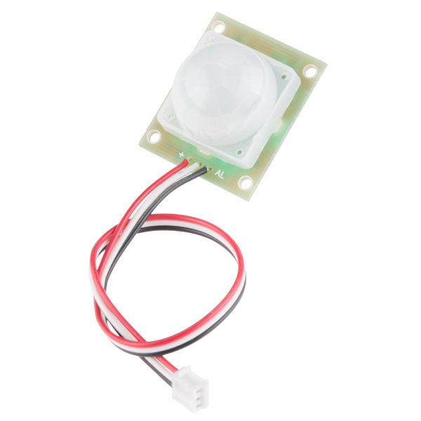
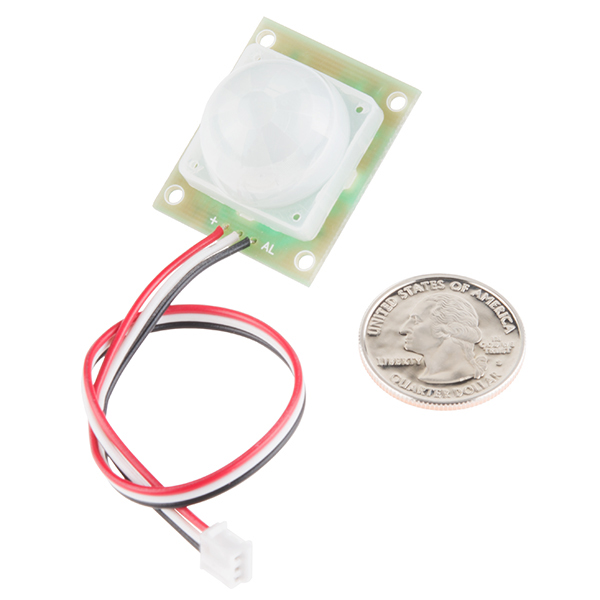
This is a simple to use motion sensor. Power it up and wait 1-2 seconds for the sensor to get a snapshot of the still room. If anything moves after that period, the 'alarm' pin will go low.
This unit works great from 5 to 12V (datasheet shows 12V). You can also install a jumper wire past the 5V regulator on board to make this unit work at 3.3V. Sensor uses 1.6mA@3.3V.
The alarm pin is an open collector meaning you will need a pull up resistor on the alarm pin. The open drain setup allows multiple motion sensors to be connected on a single input pin. If any of the motion sensors go off, the input pin will be pulled low.
We've finally updated the connector! Gone is the old "odd" connector, now you will find a common 3-pin JST! This makes the PIR Sensor much more accessible for whatever your project may need.
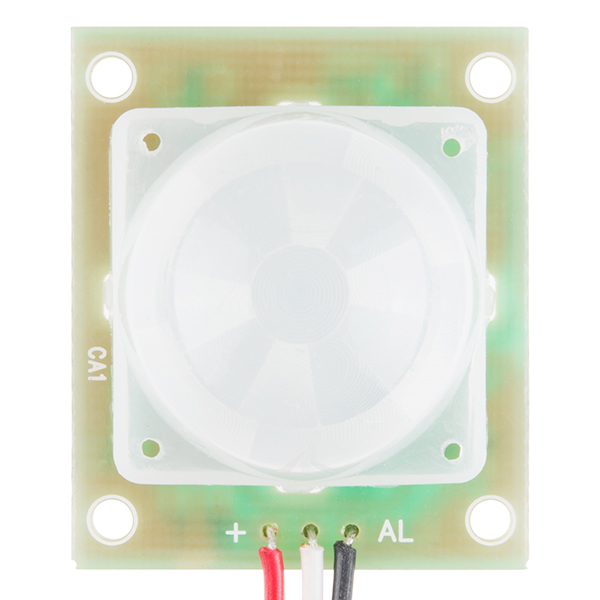
- Red = Power
- White = Ground
- Black = Alarm
PIR Motion Sensor (JST) Product Help and Resources
Photon Remote Water Level Sensor
June 2, 2016
Learn how to build a remote water level sensor for a water storage tank and how to automate a pump based off the readings!
SparkFun Inventor's Kit for Photon Experiment Guide
September 3, 2015
Dive into the world of the Internet of Things with the SparkFun Inventor's Kit for Photon.
RedBoard Santa Trap
December 25, 2014
A fun holiday project to try for anyone looking to catch Santa on Christmas!
PIR Motion Sensor Hookup Guide
May 5, 2016
An overview of passive infrared (PIR) motion detecting sensors, and how to hook them up to an Arduino.
1 of 1 found this helpful:
Bypassing the voltage regulator
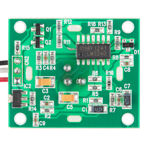
The PIR motion sensor can work with at least 5V. However, the voltage may not be enough for the L78L05 voltage regulator to work reliably depending on your power supply. You can try to bypass the voltage regulator if this is the case. To bypass the voltage regulator, you would need to solder some jumper wire on the PIR motion sensor so that 5V bypasses the voltage regulator's Vout pin. Just add a jumper between the pin connected to the RED wire/Vin pin and the regulator's Vout pin. For more information, check out this note from the PIR Motion Sensor Hookup Guide.
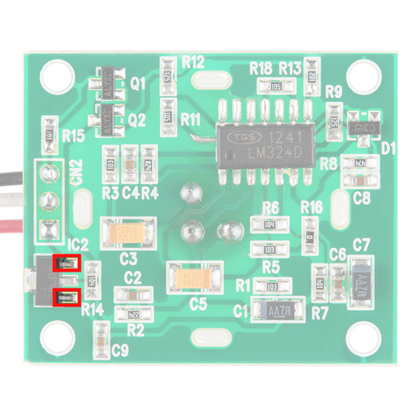
You can also try looking at the general datasheet for the L78L05 voltage regulator that is on the PIR sensor for the pinouts or specs.
Core Skill: Programming
If a board needs code or communicates somehow, you're going to need to know how to program or interface with it. The programming skill is all about communication and code.
Skill Level: Rookie - You will need a better fundamental understand of what code is, and how it works. You will be using beginner-level software and development tools like Arduino. You will be dealing directly with code, but numerous examples and libraries are available. Sensors or shields will communicate with serial or TTL.
See all skill levels
Core Skill: Electrical Prototyping
If it requires power, you need to know how much, what all the pins do, and how to hook it up. You may need to reference datasheets, schematics, and know the ins and outs of electronics.
Skill Level: Rookie - You may be required to know a bit more about the component, such as orientation, or how to hook it up, in addition to power requirements. You will need to understand polarized components.
See all skill levels
Comments
Looking for answers to technical questions?
We welcome your comments and suggestions below. However, if you are looking for solutions to technical questions please see our Technical Assistance page.
Customer Reviews
2.9 out of 5
Based on 22 ratings:
1 of 1 found this helpful:
Super fun
This sensor works well, is a good value and was delivered quickly. I used it to trigger an Arduino with a sound shield. It works with the Arduino very well and although other people have had issues with it, I had none. I used the Arduino pinMode(INPUT_PULLUP) that uses the internal 20K pull up resistor so you do not need any external resistor. The project I used this for was a pumpkin that made sounds as people approached. It was a hit.
1 of 1 found this helpful:
It was okay
RED is POSITIVE WHITE is NEGATIVE Black is signal
I murdered this the second use after I forgot this convention. It did operate correctly the first use although requiring a pull-up resistor was strange in my opinion. I can't complain too much as I destroyed it for not following clear instructions.
2 of 2 found this helpful:
Good but DO NOT RUN ON 5 VDC THEY LIKE 9 VDC
I've been using these sensors for a bit now. Yes the wiring colors are CONFUSING just be careful.
My deal is that at 5 VDC these sensors will work - until they don't. We ran one for a long time at 5 VDC on one location, worked great. In another location, it would have bursts of false triggers about every 2 minutes. Why? I have no idea. Slightly different ambient temperature? The worst kind of failures are the intermittent kind.
Switched to 9 VDC and so far they work like a charm.
So if you are just messing around, sure 5 VDC will work just to play with, probably. If you really want some reliability, go to 9 VDC.
3 of 4 found this helpful:
Be sure to check out how it is wired
Be careful, the wire colors vary. I bought two from Sparkfun and on one of them them the Alarm wire color is white and on the other one it is black.
http://i.imgur.com/i1OJext.jpg
Our Tech Team has only seen this happen one other time. If you would like an exchange, please let us know. We'll be happy to help you. Thanks
2 of 3 found this helpful:
Not sure what I think of this
Well maybe I just don't know how to use this thing.
But it seems to be a real pain to use. First off is the black wire is the "alarm". Maybe because it is an open collector that is a reasonable color choice. I forgot at least once that it was an open collector and had to rewire.
Once I got it detecting it did fine signalling someone entered the room. But I could not figure out a way to find out once someone entered if they left. I have a complicated filter and state machine in code to try and remove the invalid blurps. It looks like after so much inactive time it sends a pulse on the alarm.
I think I will give up and search for something else, maybe buy some motion activated night lights and use them in my project.
3 of 9 found this helpful:
Terrible PIR sensor, avoid
(1) Signal wire is black, ground wire is white.
These should be reversed. I might have killed two of my sensors because the wire colors don't match up to expectations.
(2) The manual says that there should be a 10k pullup resistor on the arduino, why can't this be built into the electronic itself? The power rail is right there.
There are other PIR sensors on the market. Stay away from this one.
Hi, Pin outs for this sensor are clearly listed in the product description. (Red = Power, White = Ground, and Black = Alarm.) Sorry that this color pattern is not satisfying for you. As for the pull up resistor, some processors have built in pullup resistors. So leaving the sensor bare allows for a wider range of applications.
A learning experience...
I wired this up with an Arduino Micro. There are a lot of example programs using timers and delays. I wanted to make this interrupt driven. I had had to resolve a few self-induced logic errors in my code. Eventually, it worked. I've discovered the PIR is a little unstable at 5 volts, but works really well with 9 volts. It also seems to have a greater range at the higher voltage. I'll try 12 volts next.
Poor sensitivity, sparse data
I bought 3 of these to replace another sensor with a similar form-factor. The original sensor had no trouble sensing a moving person 4 meters away, but these don't. They work if I wave my hand from about 2 meters, which is not acceptable for my application. I'm running at 12 V.
Also, there is almost no data available. The SE-10 datasheet looks mostly like a copy of the data for the raw sensor. Where's the electrical (output lo voltage) and optical specs (sense angle)?
Sorry these didn't work to replace your other device. Let us know if you would like to send those back for a return. https://www.sparkfun.com/returns
The PIR Motion Sensor works very well.
The sensor works exactly as described in the the documentation and meets my expectations for use in my application.
Works at intended
Works well for what I'm using it for and great price.
Anyone have a link for a 3d printed case for this?
Works well
This device works exactly as I thought it would. Using it to activate an animal watering dish, and the range and width of the detection works perfectly. I just wish there was a cover available for it.
Finicky
I had trouble getting this to work correctly. It would trip regularly for no apparent reason. The description says it needs 1-2 seconds to calibrate. The hookup guide says 15 seconds. It didn't seem to matter either way. It doesn't seem to have any sensitivity adjustments; perhaps that would have helped. I ended up selecting a different sensor type that proved far more reliable for my project.
Sorry to hear you're having trouble. I would suggest contacting our tech support team, they should be able to help you out.
Works
I bought this because it was the one PIR I could find that went low on motion detection. It works well, I do notice a lag, but I'm not confident that is on account of the PIR and not some other component. I did have to order a replacement after frying the first one. Despite reading the hookup instructions and the other comments on the unusual wire colors, I still managed to fry it because the JST connector I hooked it up to had a different wire color order. Stupid mistake, but I guess that's why you should triple check everything before hitting the on button.
Excellent door bell trigger for my outdoor cat!
Paired this sensor with a Photon from Particle to enable my outdoor cat to request entry. Motion sensitivity is great, but position is everything. Except for the occasional leaves blowing in the garage, not many false positive triggers at all and a very effective door bell trigger for my cat. Thanks guys!
Dead on arrival
Had to borrow a spare PIR sensor from a friend after mine arrived dead in the mail. Almost got screwed over on a school project.
I am stiill trying to get it to work
i had it hooked up to an LED and it was flashing like crazy whether there was motion or not. Then I found this site http://bildr.org/2011/06/pir_arduino/ and added the resistor and the code from the site. It stlill didn't work, there was no output on the screen saying "motion detected" I am using an Arduino uno, any ideas as to what I'm doing wrong? Thanks in advance. I've loved all the other products I've ordered from you including the Drum kit Kit ai - I got that working without any problem.
Hi, It sounds like you should get in touch with our Technical Support team. They'll be happy to try to help you get up and running. Tech support @ sparkfun .com
Order came with 1/3 components
This isn't just a review of the PIR Motion Sensor. I ordered this with the Termistor and Load Sensor for class....got billed for all three however only the motion sensor came. Of course I only opened it when it was required for class so now I'm behind.
Thanks SparkFun!
Head over to www.sparkfun.com/returns and fill out the form and we'll get ya taken care of!
Thanks for reminding me that it has awkward color coding for the cables. It is something that definitely can be/should be fixed for a sensor priced at $10 dollars. The cable should not be advertised as a new feature until the color coding is fixed.
I bought two sensors. The sensors work but it can be more consistent and sensitive. Sometimes it would recognize a hand quickly, sometimes its totally ignored. I am not sure if its picking up the reflection of IR in the room so when a hand is placed closely to the front of the sensor, it still would not register a "change".
0 of 1 found this helpful:
This motion sensor's detection distance is horrible. I connected it to my Arduino and it only senses it if I'm touching it or like 1 millimeter away...
It sounds like you have a bad unit, or a connection issue. Please contact our support team and they'll be happy to help you out.
0 of 1 found this helpful:
Nice Product!
Working good so far! I'll let you know how it goes... ;-)
0 of 6 found this helpful:
Cheap, but pretty useless.
Does what it needs to.
0 of 2 found this helpful:
Have not been able to make work
Like other users have said mine came wired with the red for alarm and the black for power. This is not like the directions say it should be. Also no matter how hard I have tried I can not get it to work for my Raspberry Pi 2. Good luck to anyone else who tries this.
Hmm, interfacing this with an RPi2 should be fairly straightforward. I would suggest contacting our tech support team, they should be able to help you out.
Hi, hope you’ll find this interesting : http://www.instructables.com/id/The-Flying-Manatee/ It’s using sparkfun micro size servo and Pir.
It's not a motion detector. It does not "see" movement. It looks at a target and sets itself to that. When a hotter or colder temp is detected the signal pin is switched. In a commercial PIR there is a counter which is used in conjunction with a segmented lens. As the warm or colder target is seen through the lens, the counter is incremented. When the preset count is reached the support circuit switches a relay that is wired to an alarm panel. The major problem with PIRs is not being installed correctly. Sun light creeping across a floor or the warm air from a heater vent can set them off. If you have a cat and want to use one of those, be ready for a pot load of false alarms. They climb everywhere and it's impossible to compensate for them. And if you want to use them for open air surveillance, they don't do too well. Better to have a fixed object like a wall in the field of view.
I designed and installed high end security systems for 25 years.
Update: After a lot of consultation with Sparkfun tech support I was able to trace the problem to a faulty oscilloscope that I was using. This sensor does, in fact, work when supplied with 3.3v. Just be sure that the power is clean because any sort of noise will trigger false alarms.
Original comment: Despite what the product description says, this will NOT operate at 3.3v even if you bypass the regulator. The circuit needs a full 5v to operate, so you need to supply exactly 5v if the regulator is bypassed, and if not bypassed, you need to provide >7v. If the voltage is too low, it will constantly and randomly bring the alarm pin low, regardless of what the sensor sees.
I got this sensor from a while, however i have some question on it , in the board there is '+' an 'AL'in my sensor the '+' is connected with black wire, 'AL' with red wire but in the description: Red = Power, White = Ground, and Black = Alarm. my question is what is the correct connection, what is in my board or the description????
Thanks
Wow! What an incomplete datasheet that one is! I mean, why do the manufacturer omits such relevant data as distance range of operation? 3m? 3ft? What? A mostly empty sheet with a nice pic of the module and a few bits of info in a corner. Wow. Just wow!
I tried running at these at 5V and they behaved erratically (5V isn't enough to power the regulator.) Then I tried bypassing the regulator and powering it with 3.3V, again the sensor would go of for no reason (even the smallest amount of noise on the power would trigger the sensors.) I then hooked the regulator back in and just supplied it with 12V and it worked as it is suppose to.
I can't tell from the datasheet what kind of ranges it can handle. Obviously in the video the hand is less than a foot from the sensor, but what about 20 feet? 40 feet? 1000 feet?
The only thing I could find was 3-7 meters. Depending on how good the lens is they can see 30 meters but I'm not sure on this one. It's made by Hanse and they don't have any better datasheet on their site. info
I don't know, but I would like to know as well.