SparkFun Gas Sensor Breakout
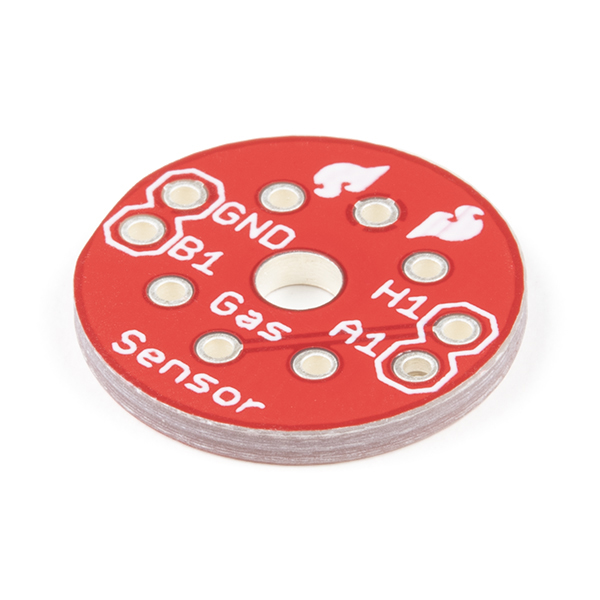
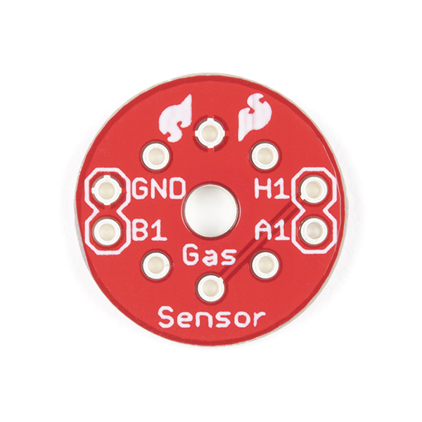
This is a simple breakout board for the MQ - 3, MQ - 4, MQ - 6, MQ - 7, and MQ - 8 gas sensors. With the Gas Sensor Breakout you will be able to utilize each oversized, oddly spaced pins featured on every MQ gas sensor product. This is an extremely handy and economical board to have around when detecting multiple types of gases.
All you need is the VCC at 5V, GND, and a resistor to an ADC, that is it!
Note: This is just the PCB. The appropriate sensors are listed below in the Recommended Products.
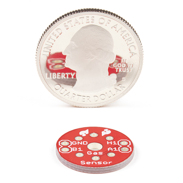
- 16.8mm Diameter
SparkFun Gas Sensor Breakout Product Help and Resources
Hazardous Gas Monitor
June 17, 2016
Build a portable gas monitor to check for dangerous levels of hazardous gases.
Core Skill: Soldering
This skill defines how difficult the soldering is on a particular product. It might be a couple simple solder joints, or require special reflow tools.
Skill Level: Noob - Some basic soldering is required, but it is limited to a just a few pins, basic through-hole soldering, and couple (if any) polarized components. A basic soldering iron is all you should need.
See all skill levels
Comments
Looking for answers to technical questions?
We welcome your comments and suggestions below. However, if you are looking for solutions to technical questions please see our Technical Assistance page.
Customer Reviews
4 out of 5
Based on 2 ratings:
3 of 4 found this helpful:
If you buy a gas sensor this is a must have
Just another example of sparkfun making necessities available. Took some reading to figure out how to hook it up and use it.
0 of 7 found this helpful:
will this work for the MQ-7 gas sensor?
The MQ-7 Carbon monoxide sensor?


Hello, I've read about gas sensors that for them to work properly over an extended period of time, the voltage provided needs to be cycled constantly within a certain range.
However, I've seen nothing about that in these comments / diagrams / code examples.
Does anyone know more about this? Thanks!
Use the SF Gas Sensor Breakout Board. The MQ-6 label should be oriented as shown in the picture of the breakout board board (to the left when looking at the bottom of the breakout board). Connect (GND TO Ground), (A1 TO +5V), (H1 TO +5V; heater) and [B1 TO (10kohm load resistor to ground) AND B1 TO (Analog pin)]. In effect you measure the difference between A1 and B1.
I made this wiring you say here but my sensor is getting hot and I start getting 660 and dropping until around 120. Does it mean that it's working? Thank you.
Hi everyone. When interfaced with UNO it gives values continuously decreasing from 1023 to down below. H1 & A1 - 5v; B1 - 10k to GND (read it from top to Anlog0); GND- GND
Hi everyone. Just managed to get a proper connection scheme for this thing. So here you go: (GND TO Ground), (A1 TO +5V), (H1 TO +5V) and [B1 TO (10kohm to ground) AND TO (Analog pin)]. Works for me. Tried it with...perfume :D
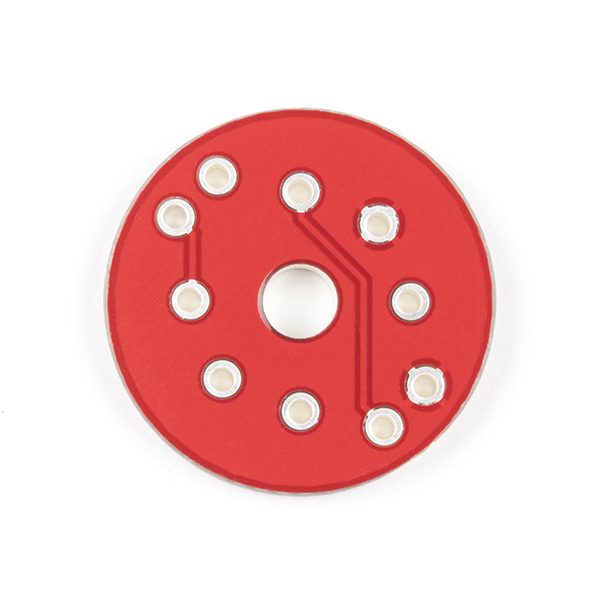
I tested the board with a multimeter's buzzer and found that both As are connected together and both Bs are connected together (see the datasheet for As and Bs). So all you need is:
H1 -> 5V, A1 -> 5V, GND -> GND, B1 -> Microcontroller's input
It would be great if you guys could carry a gas sensor socket, like this one.
i am trying to use this with the MQ-7 and can't figure out the orientation. does the side with Mq-7 sticker align with the "Gas Sensor" print on the breakout board? I tried looking for a wiring diagram on the MQ-7 but couldn't find a good response
Has anyone figured out this breakout board wiring? All the comments below seem to be contradicting one another at various points.
My guess so far is this:
I purchased two and have not soldered the second to the breakout board as I am stil unsure as to how the four pins should be hooked up. Any and all assistance is appreciated.
no, wrong. H is for heater, you need to supply 5v to heater. you will measure the difference between the signals on A1 and B1. give A1 a 5v, and measure the drop to B1. B1 needs a load (10k ohm resistor to gnd). measure the voltage on top of that load. A1 and B1 are interchangeable. as in you could supply 5v to B1, and measure the voltage drop across a 10k ohm resistor connected from A1 to gnd.
So whats the wiring diagram for this?!? Theres a wiring diagram for the sensor, but this thing has only 4 pins...
The pololu.com sensor mount seems more practical. Can Sparkfun come up with another design more easily mounted?
Quick question to SF or anyone who has one of these:
What is the pin spacing of the 4 holes? (where the wires attach in the picture) Is it a standard .1", able to be mounted on a circuit board? Also, what is the diameter of the hole in the center?
To SparkFun:
A dimensional drawing would help tremendously. (IMHO)
--Ian
That is what I'm wondering too
The Eagle files were posted - should be able to measure accurately from there. For those not able to open the Eagle files, using this image as a reference:
http://farm4.static.flickr.com/3200/5808827390_7c491116f0.jpg
X = 0.5"
Y = 0.1"
D = 3mm
Check out the eagle files. The best way to get a complete dimensional is to download the free version of eagle and check the files posted.
You might want to just look at the datasheet of any of the sensors, they have full dimensional drawings in them.
I don't mean the sensor pins, but the other 4 (gnd, A1, B1, H1).
Dimensional Drawing
X=?
Y=?
D=?
Y=0.1 inch
Thank you.
Still two dimensions left. Anyone?
I'll get the eagle files posted, which will be the exact dimensions for all the holes.
Bueller?... Bueller?...
There is 6 pin in but just 4 pin out. I just tought that 3 of the sensor pin are connected together at pin output H1 but the internal connection like as below
H one to GND
H other to H1
A one to A1
A second not connected
B one to B1
B second not connected
But other A should be at 5V
and other B should be at GND with 10K by the wiring refer.
http://wiring.org.co/learning/basics/airqualitymq135.html
could some one tell me the solution? The sensor should be hot for having efficient data. and the best wiring connection was given at above.
The connection on below should be pulled down at B to GND?
http://img55.imageshack.us/img55/6237/alchoolau5.jpg
Could definitely use a schematic of this breakout board in use. I tried a lot of diff possible ways and while I got one to show me something in the serial output the sensor was getting hot and I am sure that is wrong.
http://img55.imageshack.us/img55/6237/alchoolau5.jpg
Ignore the "A or B" label. How ever you hook it up, you measure from one side to the other. From A to B, or from B to A.
The sensor is supposed to get hot.
Hi - I am still a little confused by this. I gather H1 should be connected to +5v, and that GND goes to ground.
What do A1 and A2 connect to? I assume one to a ADC pin, and the other through a resistor to GND, but can't seem to get it to work.
It would be helpful if the diagram/schematic showed a sample connection.
Three days later:
Now that I've actually received them, however, the boards are not the same as imaged - but are correctly labeled and wired. The terminals are, on the boards I've received, labeled B1 and A1 and are properly connected to the sensor pins.
The photos here are of an incorrectly wired board, surely an earlier version. The original poster was correct, but the shipped boards are fine.
What confuses this matter is the document, which shows the part in three drawings of two orientations; only one of the three drawings, the top one with the heater pins horizontal, is electrically and physically correct. I think the original board layout fell victim to misleading documentation.
This is indeed the case, as I pointed this issue out in Dec '08 and had the boards I purchased refunded. They scrapped their remaining stock and ordered new ones, but it would seem that they never updated the pictures.
Actually, the board appears to be fine. The silkscreening is just misleading; A1/A2 should be A/B.
The photos show both sides, flipped vertically. I believe you'll see that the connections are correct.
I think this is wired incorrectly- the datasheet for the alcohol sensors states that you need to measure between one of the 'B' terminals, and one of the 'A' terminals. On the board, it looks like you are bringing out the connections for A1 and A2, which is reasonably usesless, as they are connected together in the part.