ATX Power Supply Connector - Straight
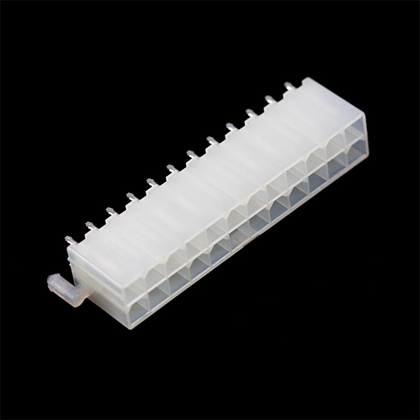
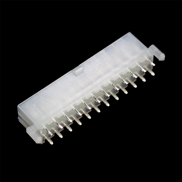
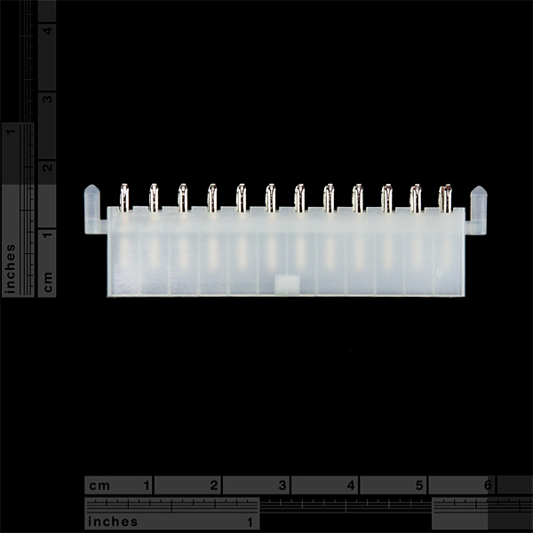
This is a 24-pin Molex Mini-Fit Jr.? connector, commonly used as the power supply connector on ATX motherboards. Two rows of twelve pins are broken out two rows of through-hole male headers. See datasheet for the pin spacings and other dimensions.
Pair this connector with a standard computer power supply and you can source a number of different voltages (+3.3V, +5V, +12V, -12V, -5V) to your project.
ATX Power Supply Connector - Straight Product Help and Resources
Core Skill: Soldering
This skill defines how difficult the soldering is on a particular product. It might be a couple simple solder joints, or require special reflow tools.
Skill Level: Noob - Some basic soldering is required, but it is limited to a just a few pins, basic through-hole soldering, and couple (if any) polarized components. A basic soldering iron is all you should need.
See all skill levels
Comments
Looking for answers to technical questions?
We welcome your comments and suggestions below. However, if you are looking for solutions to technical questions please see our Technical Assistance page.
Customer Reviews
No reviews yet.


Does anyone have an eagle file for this connector?
I have created a component file for this part in easyeda. When I get my boards I ordered using this component and it's a good test fit, I will share.
here is the link to the gerber file as mentioned above.
https://github.com/cyplesma/gerber-for-Sparkfun-ATX-24-Pin-Veritical-Connector
This needs an eagle file.
warning: this is not compatible with https://www.sparkfun.com/products/9558 - Sparkfun did not claim they were compatible, do not make the same assumption as me. You can snap off the plastic tabs at the end though, and it will fit.
Do you have a 20 pin version of this connector?
unfortunately, no, we don't. sorry.
Is this part available in the Eagle library?
Doesn't look like it. SparkFun-Connectors.lbr only has the right-angle one. Should be able to modify that Device to add the regular Package, though - all the required information is in the dimensional drawing datasheet.
At what scale should I print (on to A4) the Dimensional Drawing to get the hole layout 1:1?
I purchased this connector with the breakout board only to realize that the white pegs on the ends of the connector, do have corresponding holes on the board. Now I know.