SparkFun SerIO
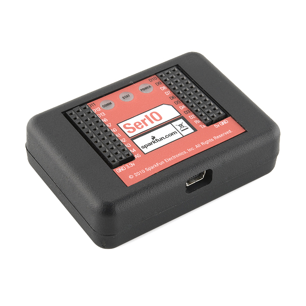
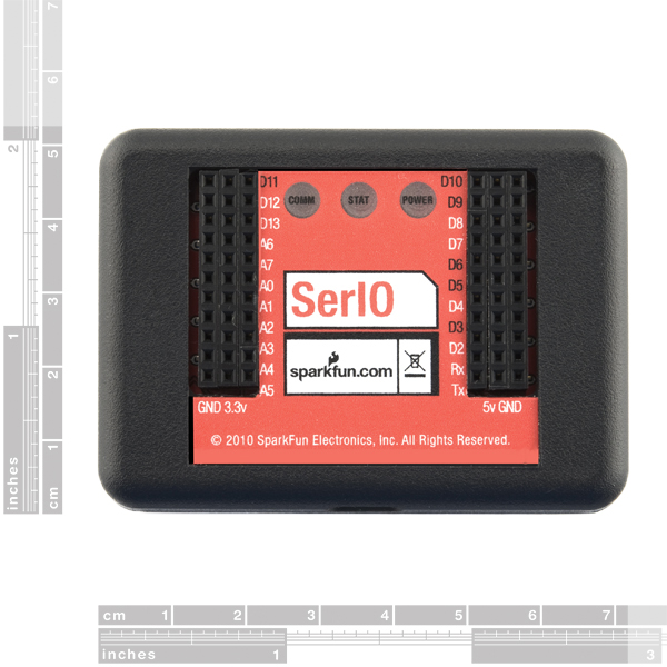
The SparkFun SerIO is a serial interface platform for creating physical computing projects controlled from a computer. The board gives access to 14 digital input and output pins, six analog output pins and eight analog input pins through a serial interface. This allows the creation of physical computing projects without having to modify and code on the hardware platform. Projects that involve the use of analog sensors, buttons, LEDs, buzzers, motors and many more electronic components can be controlled from any environment that has access to a serial port; some examples of controlling environments are Visual Basic, Python, LabView and Processing, but it's certainly not limited to those languages!
- Built with the ATMega328
- Powered from USB
- Serial Communication over USB at 57600bps, 8-N-1
- 14 digital I/O Pins
- 6 Analog Output Pins
- 8 Analog Input Pins
- Simple Serial Command Interface for I/O Manipulation
- Arduino Bootloader Installed
SparkFun SerIO Product Help and Resources
Core Skill: DIY
Whether it's for assembling a kit, hacking an enclosure, or creating your own parts; the DIY skill is all about knowing how to use tools and the techniques associated with them.
Skill Level: Noob - Basic assembly is required. You may need to provide your own basic tools like a screwdriver, hammer or scissors. Power tools or custom parts are not required. Instructions will be included and easy to follow. Sewing may be required, but only with included patterns.
See all skill levels
Core Skill: Programming
If a board needs code or communicates somehow, you're going to need to know how to program or interface with it. The programming skill is all about communication and code.
Skill Level: Rookie - You will need a better fundamental understand of what code is, and how it works. You will be using beginner-level software and development tools like Arduino. You will be dealing directly with code, but numerous examples and libraries are available. Sensors or shields will communicate with serial or TTL.
See all skill levels
Core Skill: Electrical Prototyping
If it requires power, you need to know how much, what all the pins do, and how to hook it up. You may need to reference datasheets, schematics, and know the ins and outs of electronics.
Skill Level: Competent - You will be required to reference a datasheet or schematic to know how to use a component. Your knowledge of a datasheet will only require basic features like power requirements, pinouts, or communications type. Also, you may need a power supply that?s greater than 12V or more than 1A worth of current.
See all skill levels
Comments
Looking for answers to technical questions?
We welcome your comments and suggestions below. However, if you are looking for solutions to technical questions please see our Technical Assistance page.
Customer Reviews
No reviews yet.

So where is the Ehternet version??????
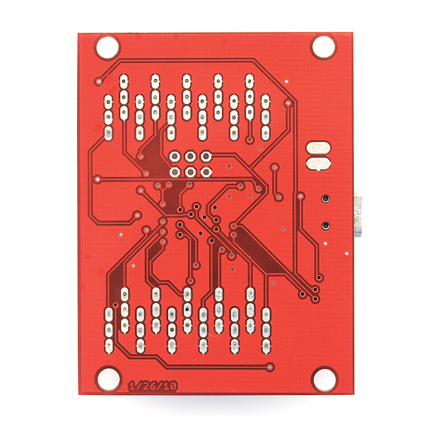
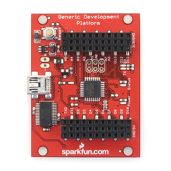
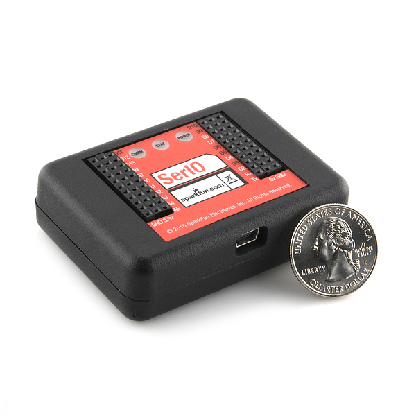
Does it come with the enclosure or do I need to buy that separately because it has pictures of it without the case and with labels on the PCB and I want to be sure of what I am buying.
What's the purpose of Q2 in the schematic?
Is this still a valid product? I am the maintainer for COMEDI in the Linux tree If the product is still real I would be interested in writing a driver for it. Currently there is only 1 serial connected driver and it's for a very old academic board. Any chance of getting a donated unit?
From the schematic, i fail to see the necessary RC circuit to create a voltage from the pwm channels (which you so wrongly call analogue outputs). You should definitely clear this up in the User Guide.
Also D0 and D1 don't appear to be accessible as they are shared with RXD/TXD which go to the FT232.
Can someone from Sparkfun clear this up?
This thing is great. I was using it, in conjunction with my laptop as a datalogger/controller ... but I may have fried it. When I plug it in, I get the "power" LED on steady/continuous, I get a couple flashes of the "comm" LED, but nothing on the "stat" LED. And, it won't respond to commands. I'm wondering what the "reset" button will do for me. Any advice on how/when to use it? Looks like I've got nothing to lose at this point.
I was looking through the source and think I found a problem with it, hoping someone can clarify.
line 167 - if(command_buffer_count == (2*MAX_COMMAND_LENGTH))return 0; //If the command is too long, exit the function
Why 2*MAX_COMMAND_LENGTH? Are you not going to write passed the end of command_buffer and possibly overwrite something, if a command longer than MAX_COMMAND_LENGTH is accidentally sent
should it not be
line 167 - if(command_buffer_count == (MAX_COMMAND_LENGTH))return 0; //If the command is too long, exit the function
I was trying to find the resolution (in bits) and speed of the Analog In ports. The manual's discussion of resolution is awfully confusing in that it seems to contradict itself. It says the voltage between 0 and 3.3V is given in 255 steps, or 8-bit resolution. It then shows how to calculate voltage from the digital reading. When it does, it divides the reading by 1024, not 254 prior to multiplying by 3.3 V. This gives an answer in 10-bits, doesn't it? Which is the right resolution, 8 or 10 bits? I couldn't find the conversion rate anywhere. What is it, please?
Can these be used with Labview instead of the NI CompactDAQ modules, or the USB-1208 from Measurement computing?
If anyone is willing to donate one of these, I'd be willing to write up a nice C# windows GUI for this as well as a command line version .exe and open source them both and let you link them here. Alternately I could do the same in Labview as well.
Ive got to say, this is a nice product. All I would want is a option to disable all of the words in the responce. I wish to implement this into C#, and all of the chars like"Pin:" are not necessary for it. Its small and could be worked around, but otherwise nice product.
Sparkduino?
Actually, such boards are just named Sparkfun and then the model, just like Arduino does it.
I DO NOT D0 WORK AND D1 PORT OF SERIO, WHICH CAN BE THE PROBLEM?
From what i can tell, D0 and D1 will never work. As they are shared with the UART which goes to the FT232R.
I DO NOT WORK AND D1 D0 PORT OF SERIOUS, WHICH CAN BE THE PROBLEM?
Both the features page and the User Guide state that there are 6 Analog Outputs. However the User Guide only lists D3, D5, D6, D10 & D11 as Analog Outputs. I am assuming from the images provided that D9 is also an Analog Output.
I wrote a simple software in Visual Basic to interface with this device, if you're interested: http://teckst.com/js/SerIO_Interface_v1.2.zip
It includes source files with SerIO Class so feel free to modify it for your own project!
I am a half-noob. I ordered this SerIO piece for a project where im going to be using it to interface a little device to my PC so that i may computer control it.
Are there any tutorials or libraries on the VB code to use and/or how to do it?
Please help? it would be much appreciated!!!!
Long live the sparkfun!
How about in the description telling us the CPU is an Arduino Mega328 ! I had to look at the schematic to find that info.
Old Man Earl
I like it :) I may end up writing a Java library to interface with it, so that you don't have to do any low-level communication - basically emulating Arduino's own pinMode(), digitalRead(), digitalWrite, analogRead() and analogWrite()... Would be nice to be able to develop for my Arduino using Eclipse :)
Anyone out there would be interested in this?
I've ordered one of these for work and plan on interfacing with labview. In anticipation of it's arrival, I've written the necessary subVI's to get the data out of it but I still don't know what the serial port settings will be? This isn't entirely necessary to know ahead of time but it might have been something nice to put into the user guide. Also the ADC formulas in the guide are a bit tough to read. Thanks to Sprakfun for putting something like this together.
Mike
The settings are 57600, 8, N and 1. Good luck with your Labview Application, please feel free to share it when it's completed.
I'm quite curious about this product, I can think of a number of things I might use for it. But I'm unclear what kind of baud rate this is capable of, when you're trying to sample analog ports, digital ports and maybe output some data as well. Seems like you might be dealing with fairly modest values.
The baud rate is 57600bps; you should be able to determine if this supports the amount of commands you want to send.
Why would you buy a board specifically for serial I/O that uses FTDI? If you want a serial I/O board, get a Teensy. It's smaller, cheaper, has 12 analog inputs, and has native USB support for full-bandwidth I/O. Google for Adrian Freed's micro-OSC code for the Teensy.
These are completely different products. The Teensy has its uses, but is harder to use without headers and such. Both have their merits.
I've been looking through the source code they posted... it's not quite a Duemilanove. The comments say it's equivalent to an Arduino pro @ 3.3v/8MHz. Either way, I just flashed the code on to my Duemilanove and it works great.
I will say, I'm going to try out some robotics stuff with this firmware tomorrow and the layout of SerIO would make connecting the PWM devices way easier. I may have to get one for that project rather than proto-boarding it.
This looks interesting as a platform to plug Vex accessories into:
<http://www.vexrobotics.com/products/accessories>
Most Vex products should plug right in and work., though you'll have to take care what you plug in where, since half the ports are 3.3V and the other half are 5V.
You should be able to plug Vex Limit Switches and Bumpers into any port. Vex LEDs and Potentiometers should be used in the 3.3V ports. The Vex light and sonar sensors may work in a 3.3V port, but I'm not sure.
It would be great if servo-style PWM were added to the command set, since the 3-pin ports are arranged correctly for servos.
Anyway, just thought I'd point this out as an interesting product intersection.
Cheers,
- Dean
I am interested in this idea Dean, but I am a beginner. So I am hoping for a clarification.
Would I be able to simply plug this into a USB (only for power), plug a Vex sensor into an input, then plug a Vex Motor the the corresponding output, and expect them to be fully operational?
If so, could I even plug the USB into a wall for power using something like this?: http://www.jr.com/cables-unlimited/pe/CBU_ZIP_hy_PWR_hy_AC/
I don't have the experience to write any type of code, so this is why I'm wondering if the serIO can be used standalone.
-Joe
It's a mega-buspirate or a mini wiring ( http://wiring.org.co/hardware/ ). I do hope it has a higher baudrate than the Arduino. Wouldn't it be cheaper to get rid of the FTDI and use an AVR or PIC with native USB ?
AFAIK the FTDI chips are the most reliable way to get USB-serial working on non-Windows platforms.
So basically it's an arduino with a bitlash alternative isn't it?
328 pre-loaded up with a command interpreter...
Mowcius
so basically its the arduino duemilanova rebuilt to include a power and ground bus for all i/o pins, and already in a project case?
This box doesnt require any MCU programming so it's a lot easier to use. I would have loved this before I even knew what MCU was.
show me where it requires no MCU programming. it has an arduino based sketch loaded, and they have 2 other user loadable sketches linked. the only major difference i see between this and a duemilanova with the SerIO sketch, other than an extra $15 for the case, is the A6 and A7 pins are broken out for use. If this were sold as board only, i would gladly buy it.
If you want I can write you one in Visual Basic for free.
yes please!
I would actually love one in C++, but anything in a .exe would be useable
Those two programs are Processing sketches, not Arduino Sketches. You run them on your PC to interface with the SerIO; no firmware needs to be uploaded to the SerIO.
If you've never used processing you should check it out; the Arduino IDE was based on it (or built on top of it, I'm not sure), and it's a great way to add some data visualization to your project:
http://processing.org/
thanks! and from what im seeing, the arduino platform IS the prodessing platform, just specially designed for the arduino
to be honest, if it came with a pc side app for interfacing and controlling it, other than the serial monitor in the arduino sketchpad IDE, i would definately buy it for that and the two extra analog pins