Bus Pirate - v3.6a
The Bus Pirate v3.6a, created by Ian Lesnet, is a troubleshooting tool that communicates between a PC and any embedded device over 1-wire, 2-wire, 3-wire, UART, I2C, SPI, and HD44780 LCD protocols - all at voltages from 0-5.5VDC. This product eliminates a ton of early prototyping effort when working with new or unknown chips.
Working with the Bus Pirate is simple and effective - type commands into a terminal on your computer, those commands are interpreted by the Bus Pirate and sent via the proper protocol. The Pirate will also interpret data sent from your embedded device back to your computer terminal. A big bonus is the bootloader installed on the PIC, which allows you to easily update the firmware and change the functionality of the board.
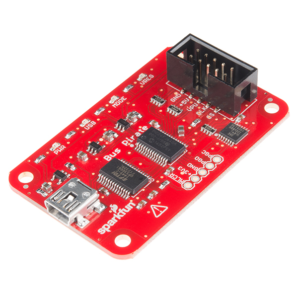
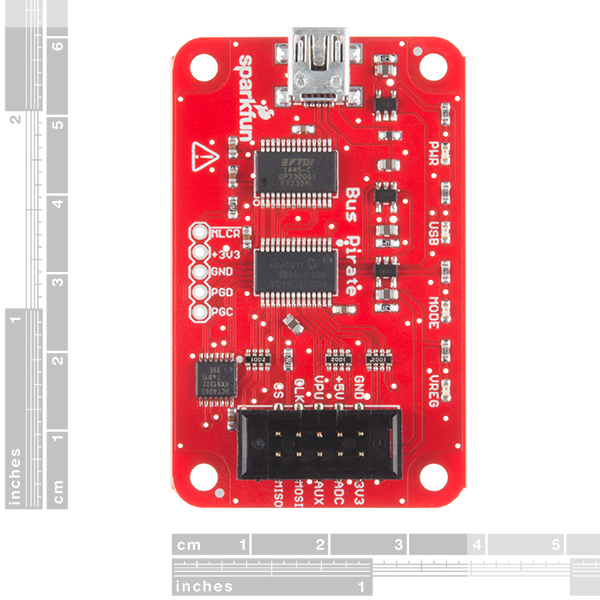
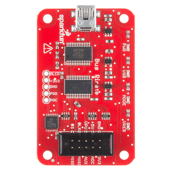
The main components of the Bus Pirate are the PIC24FJ64 processor and a FT232RL USB-to-Serial chip. A Mini-B USB connector that has also been populated on the board, provides the power to the Bus Pirate and allows you to interact with via your PC. The major difference in this version of the Bus Pirate comes from the shrouded 0.1" pitch 2x5 pin header, which has been flipped around to help standardize this board. Additionally every pin on this header has been labeled, eliminating the need for a separate I/O pin description document like with earlier versions.
Note: We sell a handy cable to connect the Bus Pirate to the system you are developing, debugging, or reverse engineering.
Note: This product is a collaboration with Ian Lesnet. A portion of each sales goes back to them for product support and continued development.
- Supported protocols:
- 1-Wire
- I2C
- SPI
- JTAG
- Asynchronous serial
- MIDI
- PC keyboard
- HD44780 LCD
- 2- and 3-wire libraries with bitwise pin control
- Scriptable binary bitbang, 1-Wire, I2C, SPI, and UART modes
- 5.5V tolerant pins
- 6V measurement probe
- 1Hz - 40MHz frequency measurement
- 1kHz - 4MHz pulse-width modulator, frequency generator
- On-board multi-voltage pull-up resistors
- On-board 3.3volt and 5volt power supplies with software reset
- Macros for common operations
- Bus traffic sniffers (SPI, I2C)
- A bootloader for easy firmware updates
- Transparent USB->serial mode
- 10Hz - 1MHz low-speed logic analyzer
- Scriptable from Perl, Python, etc.
- Access to PIC24FJ64 ICSP programming port
Bus Pirate - v3.6a Product Help and Resources
MIDI Communication with the BusPirate
The tutorial to communicate via MIDI can be found here.
Core Skill: Programming
If a board needs code or communicates somehow, you're going to need to know how to program or interface with it. The programming skill is all about communication and code.
Skill Level: Rookie - You will need a better fundamental understand of what code is, and how it works. You will be using beginner-level software and development tools like Arduino. You will be dealing directly with code, but numerous examples and libraries are available. Sensors or shields will communicate with serial or TTL.
See all skill levels
Core Skill: Electrical Prototyping
If it requires power, you need to know how much, what all the pins do, and how to hook it up. You may need to reference datasheets, schematics, and know the ins and outs of electronics.
Skill Level: Noob - You don't need to reference a datasheet, but you will need to know basic power requirements.
See all skill levels
Comments
Looking for answers to technical questions?
We welcome your comments and suggestions below. However, if you are looking for solutions to technical questions please see our Technical Assistance page.
Customer Reviews
4.4 out of 5
Based on 18 ratings:
1 of 1 found this helpful:
Really handy device
I needed to have a quick and easy means of testing an I2C interface for a work related project. I came across the Bus Pirate so ordered one. Simple to set up with the help of the tutorials and had it up and running in the lab in no time. I've not tried the other interfaces as yet, but I've been extremely pleased with what I needed it for.
3 of 3 found this helpful:
Outdated firmware does not support pyBusPirateLite
The module is shipped with the "latest" Dangerous Prototypes firmware, version 3.6. The community picked up support for the firmware after Dangerous Prototypes dropped it. The current version (dated 2016!) is V7.1, and is required to run the python "driver" pyBusPirateLite. As a terminal driven manual device it works fine, in binary mode not so much. It appears that to load V7.1, you must build the code using Microchip development environment (free, but a hassle). see https://github.com/BusPirate/Bus_Pirate. It would be great if Sparkfun either a) shipped the board with the upgraded software or b) built the firmware and posted it, the loader, and instructions on their web site.
1 of 1 found this helpful:
Best 30 bucks I ever spent
Needed to develop a 9 bit serial library for DotNet and Arduino. Bus Pirate was the perfect tool for the job. Easy to setup, worked perfectly with the OLS logic analyzer software. No glitches or workarounds needed. All for thirty dollars.
3 of 3 found this helpful:
Good product, SOLID customer support
I bought a bus pirate over a year ago, and when I finally got it out to play with, it didn't work and failed the self test. Spark fun sent me a replacement 14mo later, free of charge, no questions asked.
The bus pirate is very handy, and spark fun is worth buying from.
3 of 4 found this helpful:
What a handy tool
I was able to get a couple of I2C peripherals figured out in an afternoon. It's great to be able to play around without having to write a line of code. I'm almost didn't buy one but I'm sure glad I did.
1 of 2 found this helpful:
Very helpful and easy to use
Used the Bus Pirate to test UART. It only took a few minutes to set up this tool and confirm that UART was working. I look forward to using this tool to test my future projects. Amazing product overall!
1 of 3 found this helpful:
This is a nice little board.
It came right up when I got it and I think I'll use it.
On the pro side, There appears to be a large number of python scripts for working with various parts. The rest of the documentation is voluminous.
There are a few issues that I have with it, however.
The first issue is that it will only work when plugged into a USB port on my laptop. This could be my issue in the form of my lack of knowledge about USB but I do have other devices that just work on my hub. If every device needs to plug into the PC instead of a hub, there are not enough USB ports to do everything that I'd like to do at the same time. It comes up with the red led light by the USB labeled LED on the bus pirate when plugged into a hub. It also won't come up with Terra Term without getting in and seeing what serial port it connected with.
Another issue is that most of the parts with which it would communicate are surface mount devices. That makes it hard to use it with those devices without making a board for them or wiring them up which would be a complex and intricate task.
The manual isn't perfect either. For example, after a mode is entered, how does one exit that mode? While, I just figured that out, it isn't clear from the help menu & I had to spend time that I probably shouldn't have to get it to work.
Regardless, it appears like a tool that I will be glad to have in my tool box once I've played around with it for a bit..
Potentially very useful
I occasionally work with devices that connect over I2C or SPI. I haven't done anything with the Bus Pirate yet except pinging a QWIIC range finder ( https://www.sparkfun.com/products/14539 ) and a bit of bus sniffing. The main problem I have is that the documentation is fragmented and is all web pages. A pdf with everything would be a big plus.
Great little device, used it to install coreboot
It did come with old old old firmware, but after some google-foo was able to find a newer one from the community. Works like a charm!
This is a must-have for anyone digging in to the lower parts of the hardware stack
This is a great way to get familiar with serial ports, i2c, LCD driving, firmware flashing, and a host of other lowlevel protocols.
Plug it in to your USB port and connect to the USB-> serial interface and you get a nice text menu and lots of different modes. Don't forget to buy the d-block breakout cable for this
This is my second bus-pirate purchase - bought for a buddy who is just getting in to electronics again after a long hiatus. He loves it too!
0 of 6 found this helpful:
Really!?!?
Either I am the dumbest person in the world or this thing is the worst purchase ever!
I followed the hookup guide to the letter and the functionality is so basic. For example, I was able to wire up a MCP23017 and enter I2C mode. From there I turn on power (W) then turned on pullups (P). Okay great right? So I scanned for addresses and found 0X40. I issued some bits needed to turn GPIO to outputs then turned on some LEDs. No problem so far.
Then I head over to Dangerous Prototypes, this documentation is so outdated and no longer is supported. His videos are from along time ago even. I downloaded OLS to my mac and struggled to make it even open. Okay now what? So I watched some old youtube (the only ones out there) and tried to see if I can even get some data to capture. Yeah RIGHT!!!! This thing is so epicly not worth your money! It wouldn't even read an I2C stream from the Particle Photon. Ultimately, I wish I would have saved myself a lot of anger and frustration. Now to save nearly $200 for a better product.
Sorry about the issues and that this didn't work for you. Please contact us if you wish to initiate an RMA. Thanks https://www.sparkfun.com/returns
Neat little hacking device ;)
Ok, so not really "hacking", but the bus pirate saved my laptop after a bad BIOS flash.
I have an old ThinkPad T60 that I was experimenting with Coreboot/LIbreboot on. One of the ROMs I flashed to the laptop had a problem and the machine failed to boot! Using the bus pirate (which I was able to upgrade to firmware 6.2 beta to get faster SPI speeds), I was able to reflash the BIOS chip directly!
SparkFun's version works perfectly with flashrom and all other bus pirate tools :)
Great for decoding serial/MIDI
I'd give it 4 1/2 stars just because some of the documentation for operation and firmware versions is confusing. That being said, I'm really happy with it. While it decodes MIDI, there's not much info on the web about it, so I made a video here: https://youtu.be/ICzDtjcUjbs
Very handy for SPI.
This is the second one I’ve bought. The first never worked. I needed to get a SPI interface going so I just bought another one. It worked as advertised and was quite useful. I’ve only used it for SPI as master. It did that well. I used the Terminal interface with TeraTerm. The only issue I had was that I expected the CS to change with the sending of data. It is completely manual. SF tech cleared me up on that one. Docs for that need some clarity. Great value.
Bus Pirate: What a GREAT device!
Seriously, I tend to over engineer and take the hard road way too often - always figuring out how to do stuff my own way. But, that's NOT always needed and can be counter productive. So, sometimes, it's nice (and more efficient) to relay on someone else's expertise to make your life easier and folks at Dangerous Prototypes did just that with the Bus Pirate! Saves me time every time I need to find some dumbass i2c address or just need to twiddle something when checking out a new part. If you don't have one YOU SHOULD!
I needed to read a DS2431 EEPROM, this was the right toy for the job!
I needed to read some DS2431 EEPROM chips and Sparkfun was right down the road from me. I am using Windows so I found this tutorial: http://dangerousprototypes.com/docs/Bus_Pirate_101_tutorial, and Downloaded TeraTerm 3.1.3 as instructed in the tutorial. Once set up, it worked like a champ. TeraTerm works great as an interface, but when using Serial it only has COM1-COM12 in a dropdown list. They Are static and not dynamic. Being as I connect several different arduino boards to my system, windows starts reserving them. The Bus Pirate was assigned to COM30 something in windows, I just went into device manager, Bus Pirates com port properties and assigned it a COM Port within TeraTerms 1-12 range, made sure all of the other settings we as they should, loaded TeraTerm, setup the Serial connection, Typed M into the terminal and hit enter, and Bus Pirate menu on command. I believe you have to type capital M. I have some other stuff i want to play with this with. It is nice having SParkfun right down the road when a project comes calling for something special like this.


The Bus Pirate started out with pretty poor documentation and since Dangerous Prototypes hasn't supported it for many years, it is basically abandonware at this point. Even with a DIY firmware upgrade (which requires a $225 Microchip MPLAB programmer) it still does not support JTAG with the serial interface. Save your money for a more full featured debugger that is SUPPORTED by the people who made it. (Note that Sparkfun is blameless in this, I am aiming my ire at Dangerous Prototypes).
As another user mentioned, this v3.6 device cannot even support the community's efforts because only the v4 bus pirate has enough memory for the latest firmware.
Bus Pirate v3.6a doesn't support JTAG out of the box, despite listing it as a supported protocol. You'll have to update the firmware yourself, and figuring out which version to get and how to update the device is a real pain as documentation, releases, and notes are scattered across many sites and wikis. Additionally, once you do locate a more recent firmware build, you'll discover that the JTAG support was limited to a terminal before being removed entirely. OpenOCD binary JTAG protocol support does exist on the most recent firmware versions which are too big for Bus Pirate v3.x hardware and can thus only run on the Bus Pirate v4 or later.
BEWARE: The version that says "2/10/2010" on the bottom has the wire colors backwards from what the firmware tells you they are.
You can pull the plastic shroud off and re-install it backwards to correct the error.
Don't forget to grab the cable, I didn't realise it wasn't included.
Does it handle multi master for I2C?
What "kind" of serial device does this show up as / is there a particular driver (for Mac OS X, specifically) required?
Sorry about that oversight. It has an FTDI USB to UART bridge, so you need the standard FTDI drivers for a Mac. The drivers that come with OS X work, but are flakey.
Will this work for communication between a PC and a peripheral that is only 1.8V tolerant on its GPIO and I2C pins?
Not really. I2C is open-drain, so you could hook 1.8V to VPU. You would have to modify the main processor on the Bus Pirate to run at 2.0V for it to register 1.8V as a login level high. SPI is push-pull, so as designed this will drive at 3.3V. In general I'd say this is only for use with 3.3V or 5V parts unless you use an external level shifter.
Thanks for the reply. Reason I ask is more and more sensors and AFEs are running at 1.8V native and I'm tired of setting up level shifters!
Is there any difference to the Dangerous Prototypes Bus Pirate v3.6? Looks just the same.
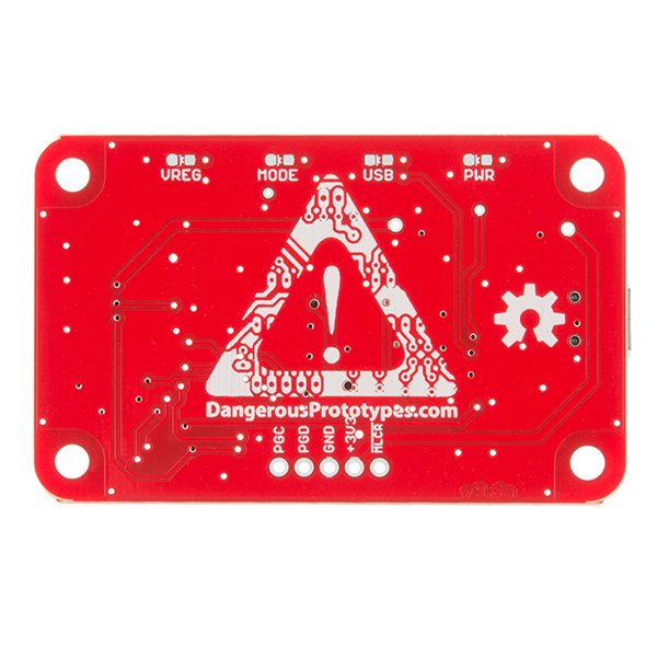
It is based HIGHLY on their design and they get a royalty. Our older version had the original wire colors that were change at some point. This is a revision to capture that change and we've added a few small improvements. Our power rails have less ripple that some customers have complained about. We also labeled the pins so the device is easier to hook up without another reference. It's largely the same thing though. Their logo is on the back:
does the mean that your version of this HW conforms to the DP6037 board outline? the image with the rulers suggests that it does not. the pervasive literature out about this suggests that it does.
They are the standard 60mm x 37mm that is the DP6037 outline. I verified that in the EAGLE files and with an actual board. We will look into why that image shows them being so much larger.
Hookup guide is 404.
Try now.
Whoo-hoo!