ShiftBrite
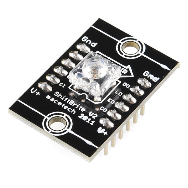
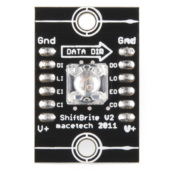
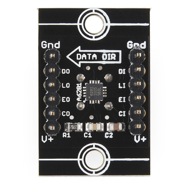
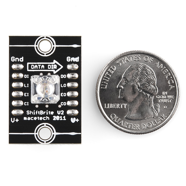
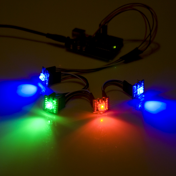
ShiftBrite is a high-brightness LED module containing red, green, and blue elements. It uses a simple clocked serial interface to receive a 10-bit brightness value for each color, resulting in over a billion possible colors. Each input is buffered and output on the other side of the module. This allows each ShiftBrite to repeat the signal to the next, allowing longer cable runs between elements without excessive loading of microcontroller I/O pins. The six input and six output pins are 0.1" headers spaced 0.6 inches apart, allowing a ShiftBrite to fit on a breadboard or wide DIP IC socket for testing.
ShiftBrite elements feature current control and automatic overtemperature control (an overheating channel driver will shut off until it has cooled). Each channel can also be adjusted with a separate current control register, for fine tuning of each LED if close brightness matching is necessary. The integrated voltage regulator powers the internal logic, allowing a single 5.5 to 9 volt supply rail to power the ShiftBrite chain.
- 8000mcd per color
- 5.5 to 9V input voltage
- 140 degree viewing angle
ShiftBrite Product Help and Resources
Core Skill: Programming
If a board needs code or communicates somehow, you're going to need to know how to program or interface with it. The programming skill is all about communication and code.
Skill Level: Rookie - You will need a better fundamental understand of what code is, and how it works. You will be using beginner-level software and development tools like Arduino. You will be dealing directly with code, but numerous examples and libraries are available. Sensors or shields will communicate with serial or TTL.
See all skill levels
Core Skill: Electrical Prototyping
If it requires power, you need to know how much, what all the pins do, and how to hook it up. You may need to reference datasheets, schematics, and know the ins and outs of electronics.
Skill Level: Rookie - You may be required to know a bit more about the component, such as orientation, or how to hook it up, in addition to power requirements. You will need to understand polarized components.
See all skill levels
Comments
Looking for answers to technical questions?
We welcome your comments and suggestions below. However, if you are looking for solutions to technical questions please see our Technical Assistance page.
Customer Reviews
No reviews yet.

Is there any reason I couldn't de-solder the LED and solder in leads so that the board could run the LED through them?
( Assuming I'm interpreting your comment correctly as wanting to have the LED in a different location from the board and soldering some wires (or a 4-wire cable - much neater) between them. )
None whatsoever. Just be careful when you desolder - that microcontroller is awfully close to the LED's pins, and they can be a pain to desolder.
Are these shiftbrite v2.0?
yes. check the pictures, it's on the silk, right below the LED.
http://mbed.org/users/4180_1/notebook/shiftbrite1/ has code examples for mbed
Could you be more specific about this "glass frosting spray"? I'm looking for a good way to diffuse Shiftbrites. Thanks!
It's just that...intended to frost glass surfaces, and labeled "Glass frosting spray" on the outside of the can. It puts down a matte, murky clearish surface that spreads light out a bit more. A quick Google search for it will turn up a variety of brands, sources, and example applications.
These would work well for color matching Vehicle instrument cluster back lighting for after market gauges.
I thought the same thing, but the color mixing isn't all that great. You'll need to do a bit of work to get the colors nice and even.
I'm going to try to use some silicone caulking over the led to help mix the colors better, but after any filter you have to be concerned with brightness.
The glass frosting spray available at hardware and craft stores works pretty well as a first level diffuser. It's mainly a clear layer with tiny bubbly structures in it that bounce light all over. I've sprayed it directly on the ShiftBrite LED with decent results.
Can I used 12 volts with this product. The Allegro A6281 datasheet says it can take up to 17 volts.
@kvan:<br /> Yes, the datasheet says 17 volts maximum. To avoid excessive power dissipation, you must limit the outputs to the range of 1 to 3 volts. This refers to the on time; obviously, the outputs will to up to the supply voltage during off time. If you have more voltage overhead than needed, you can use ballast resistors to drop the excess. From the datasheet:<br /> <br /> "Ballast Resistors - <br /> The voltage on the outputs should be kept in the range 1 to 3 V. If the voltage goes below 1V, the current will begin to rolloff as the driver runs out of headroom. At VOUT above 3 V, the power dissipation may become a problem, as each output contributes VOUT � ILED of power loss in the output sink driver. Typically the power supply nominal voltage is chosen to keep the output voltage in this range. Alternatively, series resistors can be added to dissipate the extra power and keep the output voltage within the recommended range."<br />
BTW, I was referring to the Allegro datasheet. Since the chip comes to you on a pcb with other components, the manufacturer (http://docs.macetech.com/doku.php/shiftbrite) has their own restrictions. They suggest a power supply of 5 to 9 volts.
I would like to see the next version of this with the electronics included on a pcb no larger than the LED package, with smd pads. This would make it practical for use in projects, arrays and products, and not just on a bread board.
Lots of people have used these in real projects, you can connect them with cables. SMD would significantly increase the work needed to connect these, the idea of the product was to bring an SMD chip out to pins for easier use.
Wondering if this is addressable? As in can I address individual ShiftBrites like pixels?
Yes, the modules can be connected in a long chain, and each individual LED set to any desired color by shifting out data to the complete chain. Essentially it forms a giant shift register, each LED adding 32 bits to the register. Please click the documentation link for more detailed information.
This sounds really cool, will you be stocking the LED on its own?
Ignore me - stupid moment!