×
SparkFun will be closed on Tuesday, December 24th, and Wednesday, December 25th, in observance of the Christmas holiday. Any orders qualifying for same day shipping placed after 2:00 p.m. (MST) on Monday, December 23rd, will be processed on Thursday, December 26th, when we return to regular business hours. Wishing you a safe and happy holiday from all of us at SparkFun!
Please note - we will not be available for Local Pick up orders from December 24th-December 27th. If you place an order for Local Pick-Up we will have those ready on Monday, December 30th.
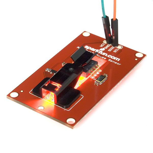
Breakout for ADNS2620 Optical Mouse Sensor
Replacement: None. It's time for this item to step down and make room in the catalog for more cool parts. This page is for reference only.
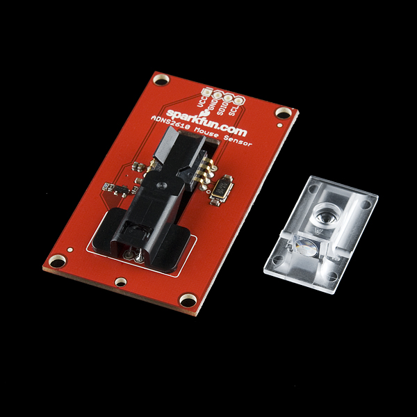
The ADNS-2620 is a small form factor optical mouse sensor. It is used to implement a non-mechanical tracking engine for computer mice. Now you can make your own optical mouse or input device.
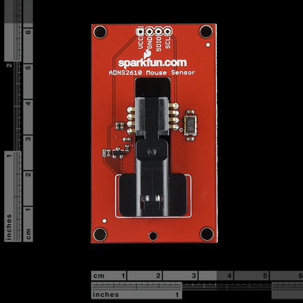
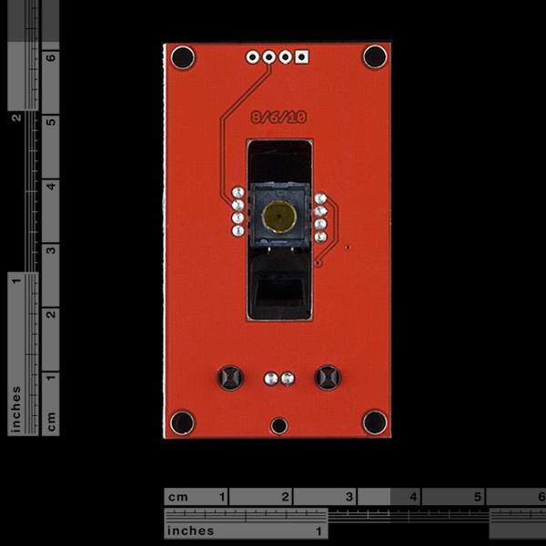
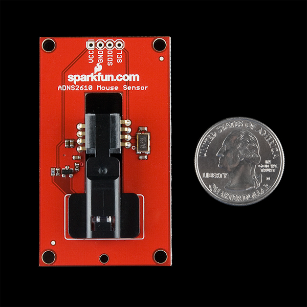
The breakout board provides you with the necessary components to get started. Check the pictures for exactly what you're getting. You get a board with the IC mounted, top clip, bottom lens, and LED. If you are looking for a more complete solution, check out the evaluation board instead.
- Schematic
- [Eagle Files](http://www.sparkfun.com/datasheets/BreakoutBoards/adns2620 breakout board v12.zip)
- Datasheet
- Datasheet (Optical Mouse Lens)
- Datasheet (LED Assembly Clip)
- Additional Design Files
- ADNS2620 Arduino Library
Comments
Looking for answers to technical questions?
We welcome your comments and suggestions below. However, if you are looking for solutions to technical questions please see our Technical Assistance page.
Customer Reviews
No reviews yet.

HI, me again. I did a small production run of a similar board for those interested. It can be found here https://www.tindie.com/products/tom10122/adns-3050-sensor-board/
Hi everyone, if anyone still wants a sensor board like this I currently have a kickstarter going for one https://www.kickstarter.com/projects/1747562424/adns-3050-optical-sensor
It uses a ADNS-3050 sensor with a higher resolution than the 2610, I also have code and 3d models to make a mouse with it.
Great sensor. worked nearly imidiatly. just dont forget to remove the kapton tape on the sensor.
Hey, I know this was a long time ago, but I was wondering if you still had the Optical Mouse Sensor Breakout. I would be willing to buy it from you for a price you name if you still have it.
Not sure if you get notifications for this or not but I have a kickstarter going for a similar sensor if you still want one https://www.kickstarter.com/projects/1747562424/adns-3050-optical-sensor
also, it appears from the avago site that the ADNS 2620 has been discontinued.
noob here, please help. is it possible to make this work with a PIC processor? i need a microprocessor AND optic sensor with low power usage. the ADNS 3000 is a low power mouse sensor, so i'd use this breakout board to test, then switch over to the actual device i want to use. it is my understanding that the arduino is NOT a lower power device as compared to some PIC models.
help out the noob, thanks.
You can use this with basically any microcontroller. The serial interface is pretty simple and the Arduino library does a great job of demonstrating how to use it. You should be able to adapt it to a PIC without too much trouble.
I have tried this sensor using the library provided together with Ardupilot with GND to GND, VCC to 5V, SDIO to Analog 4 and SCL to Analog 5. But when I try to read the X and Y from the sensor, the output will always remain FF for both X and Y. I have also try the method found in this page (http://www.flickr.com/photos/60663161@N08/5527104174/in/photostream/) saying that pin declaration where 18 = Analog 4 OR A4 & 19 = Analog 5 or A5. But the output is still FF. How can I get the readings for X and Y? Anyone manage to get the readings for the X and Y ?
In the example sketch (ADNS2620_Example.pde), try changing the line:
ADNS2620 mouse(18,19);
to
ADNS2620 mouse(A1,A0);
and see if that works better. Note that you will need the plastic lens in place in order for it to pick up movement.
do you think you could use this to reliably measure say a slick or semislick wheel odometry??
Somthing wrong with the allignment. As you can see,the led should be at the top side of the PCB instead of the bottom side. I just got one and I found the lens and the sensor can't contact closely. It's because the relative position between lens and sensor goes wrong.
I am not sure this is working:
x:FF y:FF
I connected to Analog Pins 4 & 5!
is it defective?
hi guys,
need help. i connect it to arduino Duemilanove but the reading from arduino library example only show both x & y =0, any things else I miss?
VCC to 5 v
GND to GND
SDIO to arduino analog pin 4
SCL to arduino analog pin 5
thanks in advance.
Would it be possible to get the Eagle files ? The archive only contains Gerber files.
Thanks !
Awesome, I just received my order of this. I got a mouse working and then I made a Windows app display the bitmap data from the sensor<br />
<br />
http://frank.circleofcurrent.com/index.php?page=usnoobie_adns2610
Some additional docs you might find helpful:<br />
<br />
The HDNS-2100 Lens Spec Sheet<br />
The HDNS-2200 LED Clip Spec Sheet
Good stuff. I added those both above, thanks.
Whoa, and it's within my price range, good job!
Awesome! I've been eying these things for a while on Mouser, but here they are in a nice full package. Great work SFE!
Well you guys just beat me to it AGAIN! =D well done
I was just prototyping one of these at home in order to reproduce Marko Kleine Berkenbusch's project (http://diydrones.com/profiles/blogs/quad-position-hold-
with-mouse) and use it on my own projects
I'm certainly buying these
Everyone say "low cost low res. computer vision for 8bit MCUs" ;D !
Ditto! I've been planning to prototype one of these, but the mechanical requirements (precise cutouts and positioning) have caused me to put this off time and again.
Thanks to SFE for doing the tedious work so we can make bigger/better projects!