SparkFun GPS Receiver Breakout - LS20126
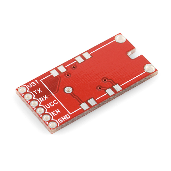
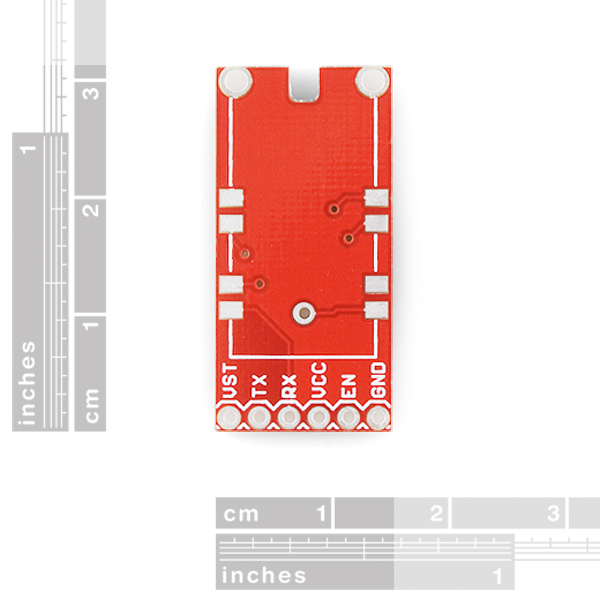
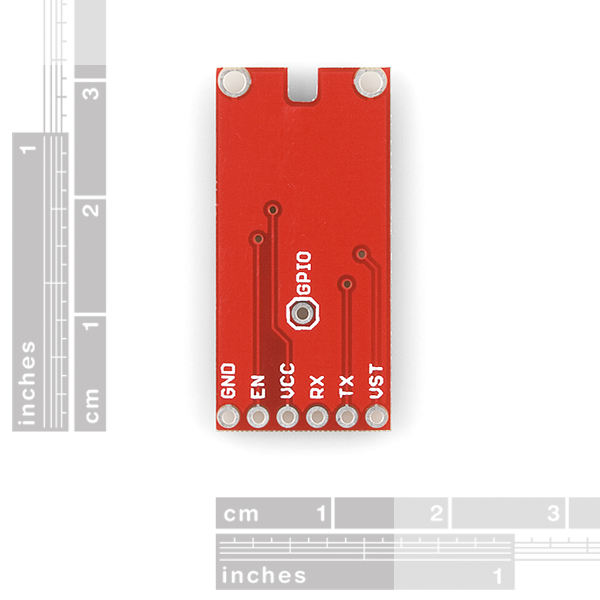
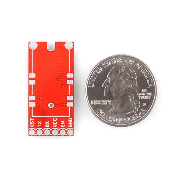
Here is a breakout board for the LS20126 GPS receiver. The board allows you to access all the pins on the GPS module through 0.1" spaced holes. Buy a header, solder everything up and you're ready to go!
The GPS module is not included.
- Schematic
- Eagle Files
- GitHub (Design Files)
SparkFun GPS Receiver Breakout - LS20126 Product Help and Resources
Core Skill: Soldering
This skill defines how difficult the soldering is on a particular product. It might be a couple simple solder joints, or require special reflow tools.
Skill Level: Noob - Some basic soldering is required, but it is limited to a just a few pins, basic through-hole soldering, and couple (if any) polarized components. A basic soldering iron is all you should need.
See all skill levels
Comments
Looking for answers to technical questions?
We welcome your comments and suggestions below. However, if you are looking for solutions to technical questions please see our Technical Assistance page.
Customer Reviews
No reviews yet.

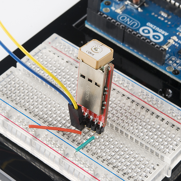
specifically, what other items do you need for this breakout board? (what kind of headers? what kind of gps module? any other parts?)
This board is designed to go with this GPS module. As for headers, the pinout on the edge is 0.1" spacing, but you can use whatever type of headers works for your application. The GPS comes with a built in antenna meaning with just the board and the GPS modules soldered (and powered) to it you should be able to get get TTL UART signal out. Any other parts would depend on what you want to do with GPS. Keep in mind that GPS module is no longer manufactured, for our current offerings check out the GPS category and feel free to email techsupport@sparkfun.com if you have any questions.
Can someone confirm that the chip antenna is indeed meant to point upwards, as in the fifth photo and as one would expect? The information in the datasheets is rather confusing.
While the antenna works better (higher gain) pointed upwards, the LS20126 datasheet indicates that the default setup expects to be horizontal, with the chip antenna pointed "forward".
If you're only using location and time, the position shown should not affect accuracy. The "heading" fields would be thoroughly confused, however.