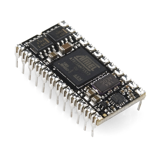
Netduino Mini
The Netduino Mini is an open source electronics platform using the .NET Micro Framework. It features a 32-bit microcontroller (the same one used in the Netduino) and has a rich development environment. The Netduino Mini has a total of 16 GPIOs with SPI, I2C, UART, 4 PWMs, and 4 ADC channels.
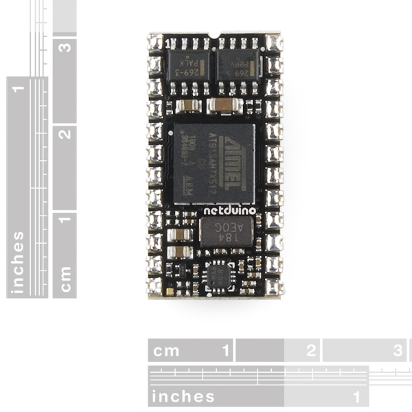
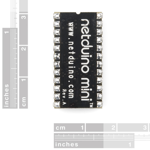
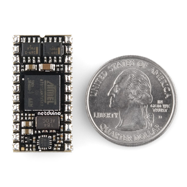
The board measures 1.2" x 0.6" and can fit easily into a breadboard. It is also pin compatible with the BASIC Stamp 2 and can be used with most of the BASIC Stamp 2 boards and kits. This is a very powerful developing platform in a very small package.
- Atmel 32-bit microcontroller
- 48Mhz, ARM7
- Small form factor
- 512Kb code storage
- 64K RAM
- Input - 7.5 - 12VDC
- Product Page
- Datasheet (AT91SAM7X512)
- Datasheet Summary (AT91SAM7X512)
- Netduino firmware
- Netduino SDK
Netduino Mini Product Help and Resources
Core Skill: Programming
If a board needs code or communicates somehow, you're going to need to know how to program or interface with it. The programming skill is all about communication and code.
Skill Level: Competent - The toolchain for programming is a bit more complex and will examples may not be explicitly provided for you. You will be required to have a fundamental knowledge of programming and be required to provide your own code. You may need to modify existing libraries or code to work with your specific hardware. Sensor and hardware interfaces will be SPI or I2C.
See all skill levels
Core Skill: Electrical Prototyping
If it requires power, you need to know how much, what all the pins do, and how to hook it up. You may need to reference datasheets, schematics, and know the ins and outs of electronics.
Skill Level: Noob - You don't need to reference a datasheet, but you will need to know basic power requirements.
See all skill levels
Comments
Looking for answers to technical questions?
We welcome your comments and suggestions below. However, if you are looking for solutions to technical questions please see our Technical Assistance page.
Customer Reviews
No reviews yet.


Very nice little chip, er, board!<br />
<br />
Not mentioned above, but an important bit of info: This can run on 7.5V-12V and provide regulated 5V out, or it can run on a regulated 5V supply:<br />
<br />
Pin 24: +VIN Input (+7.5 to +12 VDC, 9V Preferred)<br />
<br />
Pin 21: If +VIN providing power, pin 21 is +5.0V regulated output.<br />
If +VIN unused, pin 21 is +5.0V regulated input.<br />
<br />
Also, all I/O signals are 3.3V, but are 5V tolerant.<br />
<br />
Schematic is here: http://www.netduino.com/netduinomini/schematic.pdf<br />
<br />
Cheers,<br />
- Dean<br />
There has been an upgrade to the .Net Framework from v4.1 to 4.2. For those that have bought this product and it still has v4.1 in it but you would like to use 4.2 follow these links provided by Secret Labs LLC:
Here are the full instructions for upgrading a Netduino Mini to .Net Micro Framework v4.2: http://forums.netduino.com/index.php?/topic/5585-netduino-mini-firmware-v420-update-1/
The source code for the Netduino Mini 4.2 firmware is included in the "Netduino Firmware v4.2.0" Source:http://www.netduino.com/downloads/
Any clue as to when this will be back in stock?
As much as i love sparkfun, i think this is one of thier lower scoring creations. It seems to have all the standard arduino pins connected, but the datasheet shows an ethernet port, usb host, and several other unused features, completely inaccessible in the pinout. As much as i still want one, im not sure its being used to its full potential in this design.
This is made by Secret Labs, and I'm pretty sure the point is to offer NETMF in a very small (albeit fast) package.
If you need USB and/or Ethernet there are options from both Secret Labs and GHCI (FEZ) sold here.
I think this thing looks dead sexy.
You have to bear in mind the form-factor - it is designed to fit into a 24 pin socket (same as the arduino mini). That means only 24 pins to work with.
So what do you do? Drop 5 IO pins and add USB? Or drop 10 IO pins and add ethernet? How about dropping all IO for both? It's not nearly as good at controlling stuff as the arduino no matter what you do, and it is intended as a NETMF alternative to the arduino mini. Controlling stuff in a small form factor is the whole point of this little device.
I would expect to see SecretLabs produce a 30-40 pin version of this at some point that does indeed have the USB and/or ethernet pins exposed (perhaps even adapters on the board - since it will have extra room with a longer socket).
BTW, it looks like there is room on the bottom to add the USB connection to the back if they use longer pins (perhaps connecting on the bottom instead of the top?). All you need is the width of a header to do it and these nifty SMD headers: http://www.sparkfun.com/products/9015. Alternatively the board could be made slightly long and hang the USB off the back.
Either way I'd expect to see something along these lines soon, Secretlabs and FEZ both seem to be progressing pretty quickly with their hardware designs.
It's 2014... I would love to see a SparkFun-quality "cookbook tutorial" showing this and other SF-sourced parts (breadboard, battery power, etc) doing an LED blinky controller job. Something fun that could be shown for a young class or Cub Scout pack.
I don't see much use of this board except for prototyping the Atmel chip. Doesn't Atmel have an official evaluation kit for it already?
"The Netduino Mini has a total of 16 GPIOs with SPI, I2C, UART, 4 PWMs, and 4 ADC channels." To say the obvious, even most of the 8 bit Atmel chips can do all of these and why do you choose this particular chip for these basic functions? Moreover, distinct features of this chip, e.g. "USB 2.0 Full Speed Device Port, Ethernet MAC 10/100 base T, CAN 2.0A and 2.0B compliant Controller" are not accessible from this board, according to SlyVixsky.
I don't quite understand the "Netduino SDK" either. Is it supposed to target .Net developers? How is it better than Atmel's own SDK and dose it support Debugging? Microsoft dose not have a reputation in hobby uc market and Atmel are better with theis 8-bits chips.
This is a decent small embedded form factor for getting your feet wet with C# .NET micro framework development. It is really nice to be able to use the Microsoft Visual Studio tool set, with single step debugging, etc. Object oriented embedded development is sweet!
Not sure why they went with the 24-pin BASIC stamp form factor for this Mini. Recommend folks that want the features hold out for the Netduino Plus (Arduino form factor) that has microSD, Ethernet and USB capabilities, costs more but get more. Sparkfun, when will it be listed?
If you prefer C++, can give up .NET, and want a similar but larger 40-pin form factor, go with the mbed that has more pins and more features for about same price as the Plus.
seems like a mistake on the product page it says<br />
pins 1-3: RS232 TX, RX, DTR. When i wired serial crossover, pin 1 on mini to rx on the computer download wouldnt work. switched pin 1 to tx on serial cable worked ok.
That's a fundamental misunderstanding of the RS232 protocol. You have to look at the wire as either the transmit or receive wire, not the individual connections on each end, and you have to look at it from the netduino's perspective ONLY. That is because the netduino is the Data Terminal Equipment, whereas your PC's RS232 interface is the Data Communications Equipment. The transmit wire is only for transmitting, and the receive wire is only for receiving, and everything is viewed from the DTE side.
Basically what this means is that TX on the DTE (netduino here) connects to TX on the DCE (your PC or other RS232 com device), and RX on the DTE goes to RX on the DCE. For pin mapping, the TX on your device should always connect to pin 3 (TX) of the RS232 DB9 connector, and the RX of the device should always connect to pin 2 (RX) of the DB9.
So the DTE always transmits over the TX connection, and receives over the RX connection. This means, of course, that the DCE always transmits over the RX connection (i.e. the DTE needs to receive data: we don't view things from the DCE perspective) and receives over the TX connection.
Why they did it this way, I'll never know. I'm sure it made tons of sense 50 years ago, but it has been this way forever and it will never change.
The good thing is these connections only use four out of the twenty possible connections in the RS232 protocol. If that were not so you never would have fixed the problem by simply swapping the TX and RX - all of the connections are set up this way.
how do you program this thing? There is no quick start guide or other usefull information. I am guessing you would use the rs232 port?
Hi Member14940,<br />
<br />
You can program Netduino Mini via its RS232 port (pins 1 and 2) or via its 3.3V TTL UART port (pins 11 and 12).<br />
<br />
By default, Netduino Mini uses the RS232 port for programming/debugging (and the UART is available as a serial port for your code).<br />
<br />
To program/debug via the 3.3V TTL UART instead, open up a serial connection (using Putty/HyperTerminal/TeraTerm/etc.) to the TTL UART at 115200,N,8,1 and press Escape. Then select the port you'd like to use for program/debug. You'll be off and running immediately...<br />
<br />
We're working on a special "getting started" guide for the Netduino Mini--but other than using a serial port instead of USB for programming, most everything else works the same as the regular Netduino.<br />
<br />
I'll try to drop back here to answer any other questions. I'm excited to see what you all build with this tiny 32-bit module.<br />
<br />
Chris<br />
Secret Labs LLC<br />
<br />
P.S.<br />
<br />
Some RS232 connection options: RS232 cable; BASIC Stamp 2 board; USB-RS232 cable; RS232 breakout adapter<br />
<br />
Some 3.3V TTL UART connection options: 3.3V USB-TTL cable; 3.3V FTDI breakout