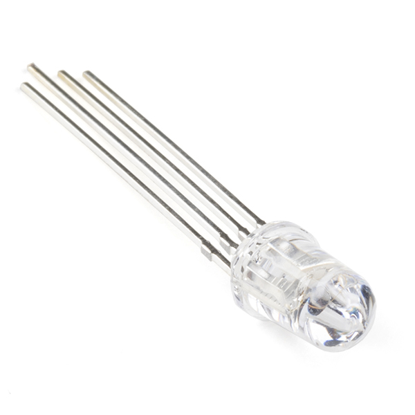
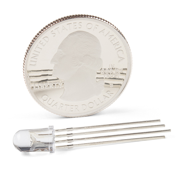
Ever hear of a thing called RGB? Red, Green, Blue? How about an RGB LED? These 5mm units have four pins - Cathode is the longest pin. One for each color and a common cathode. Use this one LED for three status indicators or pulse width modulate all three and get mixed colors!
Note: As of 1/2010, the pins in the datasheet are correctly labeled. Pin 3 is Green and Pin 4 is Blue. Those purchased prior to then will have Blue on Pin 3 and Green on Pin 4.
- Forward Voltage (RGB): (2.0, 3.2, 3.2)V
- Luminosity (RGB): (800, 4000, 900)mcd
LED - RGB Clear Common Cathode Product Help and Resources
Button Pad Hookup Guide
January 7, 2016
An introduction to matrix scanning, using the SparkFun 4x4 Button Pad.
Experiment Guide for the Johnny-Five Inventor's Kit
June 28, 2016
Use the Tessel 2 and the Johnny Five Inventors kit to explore the world of JavaScript enabled hardware through 14 awesome experiments!
Non-Addressable RGB LED Strip Hookup Guide
February 19, 2020
Add color to your projects with non-addressable LED strips! These are perfect if you want to control and power the entire strip with one color for your props, car, fish tank, room, wall, or perhaps under cabinet lighting in your home.
Core Skill: Electrical Prototyping
If it requires power, you need to know how much, what all the pins do, and how to hook it up. You may need to reference datasheets, schematics, and know the ins and outs of electronics.
Skill Level: Competent - You will be required to reference a datasheet or schematic to know how to use a component. Your knowledge of a datasheet will only require basic features like power requirements, pinouts, or communications type. Also, you may need a power supply that?s greater than 12V or more than 1A worth of current.
See all skill levels
Comments
Looking for answers to technical questions?
We welcome your comments and suggestions below. However, if you are looking for solutions to technical questions please see our Technical Assistance page.
Customer Reviews
3.7 out of 5
Based on 3 ratings:
1 of 1 found this helpful:
Nice and bright
Very nice and bright led
1 of 1 found this helpful:
Has limitations
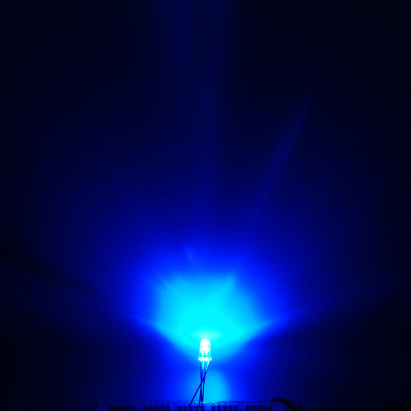
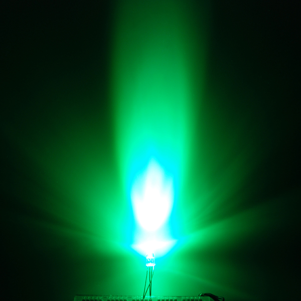
In the ones I got, there is a significant misalignment among the three colors, i.e. each color beam points in a different direction. If you just want to use each color one at a time, say as an indicator, no problem. But if you want to provide a nice blended color like yellow, they aren't very good. If you use them as an indicator, where you are looking at the LED, you see the three colors clearly and this is even worse off axis. For example if you mix red and green, rather than seeing yellow, from some angles you see mostly green, and from others mostly red. This is true even if you add a lot of diffusion. If you use them as an illuminator, where the LED shines on something else, there are three very distinct color circles rather than a blended color.
Red Light 2.2v?
FYI 3.3v will pop the red portion of the LED. The hookup guide does not show this and I quickly burnt out the RED while GREEN and BLUE accept 3.3v. Kind of odd not all are rated for the same voltage...

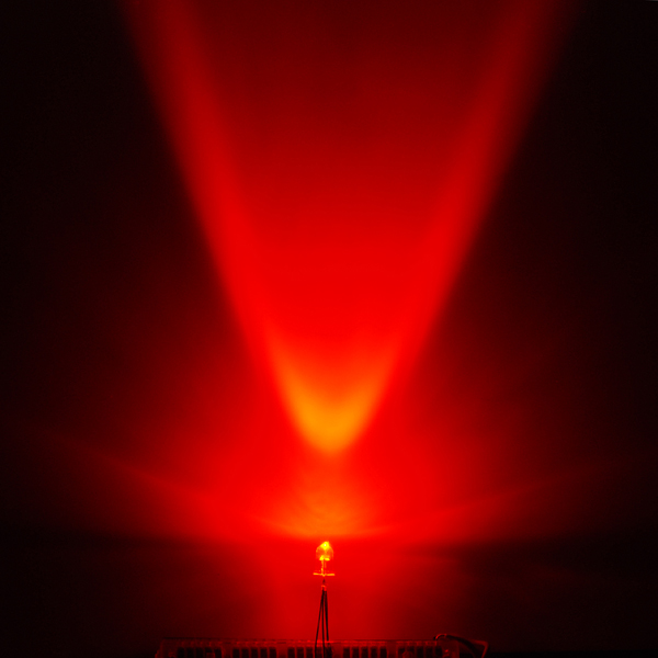
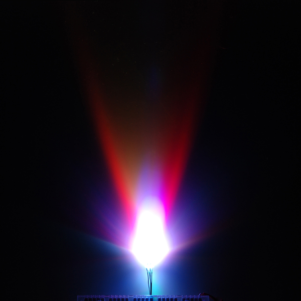
I discovered an easy way to diffuse these LEDs without permanently modifying them.
Cut a small square from the tough white foam Sparkfun ships with ICs and IC sockets. Then with an X-Acto knife, cut a small X in the underside of the cube of foam, being careful not to cut all the way through to the top. Then with scissors round out the sides and top of the cube. Stick the LED into the X you cut into the foam, and now you won't have the spotlight effect!
If you want to go back to the clear LED, just remove the foam piece.
I love these things, they're deadly awesome.
Exhibit A:
RGB LED Test Drive via Arduino from James Snell on Vimeo.
I bought a couple of these for fun. I hooked it up to the PWM channels on my microcontroller, and output a sine wave of slightly different frequency to each colour channel, and it projects a really neat cycling colour pattern on the roof when I turn the lights out! I posted a demo... kinda hard to see with my webcam, but you can see that it works.
http://www.youtube.com/watch?v=2Rm2VQqJ2tk
Digital logic uses square waves, but we know that's what you meant.
No.. Varying PWM through the correct filter, and you have a cheap DAC. Which you can use to make basic sine waves.
I didn't realize you could run LEDs off of sine waves. My mistake.
Well technically its not a true ac sine wave with positive and negative half cycles, it can only be a completely positive sine wave because like you said its digital logic which does not go into the negative scale.
You mean you did space vector pulse width modulation?
I'm making a PCB with eagle... I did not find them in it.. any ideas?
Still in the same location as a good while ago, SparkFun-LED.lbr , LED-RGB-CC-THRUCLEAR / -THRUDIFFUSE
I'm wondering how bright these are. Like could you clearly see them from 40 feet away in a well light room?
Yo soy solo un pobre esposo. me pueda Por favor comprar algunos de la electrónica de la estos. Pero no no por en la de estos caro mucho precios. la precios tienes entiendo su tienes son loco..
Te necesitas entiendo yo solo necesito un poco de estos y yo no tengo much dinero. Te necesita entiendo también muchas personas no tienen mucho dinero lo mismo. Pregunta.
¿qué tienes? ¿Qué deseas? El mundo en tu bolsillo
Yo tengo un esposa y cinco ninos todo lo que quieren es estudiar electrónica. Si usted no puede ayudar a mi esposa tiene solamente una opción. Ella debe trabajar un trabajo un muy indeseable posición para proporcionar el total de la familia con una vida mejor.
I'm driving my RGB LEDs with two shift registers (74HC595) from an Arduino Uno. After playing with some potentiometers, I found the following resistor values to offer the best color balance and highest contrast: Red: 430-Ohm, Green: 910-Ohm, Blue: 750-Ohm
Another tip that would have helped me: These LEDs are the "clear" variety (meaning they have a spotlight effect.) Sparkfun also sells "diffused" RGB LEDs. These LEDs have a much softer glow.
I found the right one, but what's up with that other one with all 4 pads all touching each other? Isn't that a short?
That has to do with Eagle's "restring" values in the DRC. Restring specifies a minimum pad size and will quietly increase pads to this size even if it's smaller in the library. Change restring to 0, and the part will work.
how?
Menu: Edit - Design Rules - Restring tab
Thank you sir I love you
Need the little cheap black plastic panel mount LED holders. Sparkfun?
We have two types of LED Holders that could work:
LED Holder - 5mm https://www.sparkfun.com/products/11147
LED Holder - 10mm https://www.sparkfun.com/products/11148
I don't see this in the Sparkfun's Eagle library. Is it there somewhere?
Yeah, we just updated it. You can find it under “LED-RGB-THRU” or “LED-RGB-CC-THRU” depending on the package under SparkFun-LED.lbr. If you are using the common anode you can find it under “LED-RGB-CA-THRU.”
To download the latest libraries just go to Github => https://github.com/sparkfun/SparkFun-Eagle-Libraries
That didn't work as nicely as anyone might hope. You can get them from here once the mirror updates in a few minutes: http://www.gedasymbols.org/user/russell_nelson/RGBLED3.fp http://www.gedasymbols.org/user/russell_nelson/rgbled.sym
I made a symbol and footprint for gEDA. http://geda-project.com/ Remember that a symbol file can't have any blank lines, so when you edit rgb-led.sym, make sure you haven't added a blank line to the end (like I did). ---------------------symbol---------------------- v 20100214 2 P 0 500 200 500 1 0 0 { T 150 550 5 8 1 1 0 6 1 pinnumber=1 T 150 450 5 8 0 1 0 8 1 pinseq=1 T 200 525 9 8 1 1 0 0 1 pinlabel=R T 200 500 5 8 0 1 0 2 1 pintype=pas } P 900 500 700 500 1 0 0 { T 750 550 5 8 1 1 0 0 1 pinnumber=3 T 750 450 5 8 0 1 0 2 1 pinseq=3 T 725 525 9 8 1 1 0 6 1 pinlabel=G T 700 500 5 8 0 1 0 8 1 pintype=pas } V 450 450 300 3 0 0 0 -1 -1 0 -1 -1 -1 -1 -1 T 800 900 5 10 0 0 0 0 1 device=LED L 516 803 617 904 3 0 0 0 -1 -1 L 617 904 621 855 3 0 0 0 -1 -1 L 621 855 722 957 3 0 0 0 -1 -1 L 484 718 585 818 3 0 0 0 -1 -1 L 585 818 589 769 3 0 0 0 -1 -1 L 589 769 690 870 3 0 0 0 -1 -1 L 300 575 300 425 3 0 0 0 -1 -1 L 375 500 300 575 3 0 0 0 -1 -1 L 375 500 300 425 3 0 0 0 -1 -1 L 375 575 375 425 3 0 0 0 -1 -1 L 600 425 600 575 3 0 0 0 -1 -1 L 525 500 600 425 3 0 0 0 -1 -1 L 525 500 600 575 3 0 0 0 -1 -1 L 525 425 525 575 3 0 0 0 -1 -1 P 400 900 400 700 1 0 0 { T 275 775 5 8 1 1 0 0 1 pinnumber=2 T 450 750 5 8 0 1 0 2 1 pinseq=2 T 400 650 9 8 0 1 0 5 1 pinlabel=K T 400 600 5 8 0 1 0 5 1 pintype=pas } L 200 500 300 500 3 0 0 0 -1 -1 L 375 500 525 500 3 0 0 0 -1 -1 L 600 500 700 500 3 0 0 0 -1 -1 L 450 500 450 650 3 0 0 0 -1 -1 L 450 650 400 650 3 0 0 0 -1 -1 L 400 650 400 700 3 0 0 0 -1 -1 T 800 700 8 10 1 1 0 0 1 refdes=LED? T 800 1500 5 10 0 0 0 0 1 description=RGB LED with common cathode T 800 1300 5 10 0 0 0 0 1 numslots=0 T 800 1100 5 10 0 0 0 0 1 symversion=0.1 L 375 300 525 300 3 0 0 0 -1 -1 L 450 300 450 200 3 0 0 0 -1 -1 L 375 375 525 375 3 0 0 0 -1 -1 L 450 375 525 300 3 0 0 0 -1 -1 L 450 375 375 300 3 0 0 0 -1 -1 L 450 500 450 375 3 0 0 0 -1 -1 P 400 0 400 200 1 0 0 { T 270 125 5 8 1 1 180 6 1 pinnumber=4 T 450 150 5 8 0 1 90 8 1 pinseq=4 T 375 325 9 8 1 1 180 0 1 pinlabel=B T 400 200 5 8 0 1 90 2 1 pintype=pas } L 450 200 400 200 3 0 0 0 -1 -1 -------------------------------footprint------------------------ Element(0x00 "LED, size in mm (pin 1 is +, 2 is -)" "" "LED5" 100 70 0 100 0x00) (
typical LED is 0.5 mm or 0.020" square pin. See for example
http://www.lumex.com and part number SSL-LX3054LGD.
0.020" square is 0.0288" diagonal. A number 57 drill is
0.043" which should be enough. a 65 mil pad gives 11 mils
of annular ring.
ElementArc(0 0 118 118 0 360 10) ElementArc(0 0 138 138 0 360 10) Mark(0 0) )
I know this is a common cathode RGB LED
Watch out for the 2V color.
I got one these from a different kit vendor but it looks exactly the same. The trouble is that for the life of me I can't get red to light. I'm assuming it is just a defective red element. Has anyone else experienced this?
i ordered many of these for my class and i confirm about 1 out of 10 have defective red elements. SparkFun should replace yours.
check you connection mi amigo, these are the same everywhere. Also clear rgb blend color not so good, como se dice the frost, oh yes diffused give you more true color.
¡Hasta la Victoria Siempre! my friend .
you may have given too much current also, then even the royal family's led no work so good
Wired one of these up to my Arduino. I didn't have a 180ohm resistor, so I wired 2x 100ohm resistors in series instead. Seemed to work just fine, though, I would strongly recommend looking at the diffused version, as you can see the distinct RGB channels in this one if you don't use a good diffusing material. That said, this thing is incredibly bright. My eyes... so shiny...
Anyways, for a couple bucks, it was neat for a short while. Get the diffused one, and the amusement becomes a lot more useful.
I'm having trouble trying to turn the red and blue at the same time, is this supposed to happen?
I'm having a similar problem. I can't get the green to turn on at all. Red and Blue work fine. Hooking up my o-scope I notice that the green lead reflects the sum of the duty cycles on the red and blue leads but at half the voltage. If I unplug the green lead the blue and red won't light at all. Hmm.. I'm pretty sure I'm just being a moron and not reading something right, but it seems pretty straight forward.
Has anyone ever tried to use these as RGB sensors? In photovoltaic mode, I seem to get reasonable voltages at R and G, but nothing at B whatsoever...
I see that the current data sheet shows pin 3 as green and pin 4 as blue but the pads in the SFE Eagle Library part appear to be labeled incorrectly for the post 1/2010 parts. The pads from left to right are labeled RED, GND, BLU, and GRN. Is this an error in the Eagle package for the part or am I missing something?
Which library are you using? I can't even find the part in the April SFE eagle library.<br />
It seems like we haven't yet updated the eagle library. I'll make a note of it.
5mm T1-3/4 RGB LED's are 4-pin with 0.05" spacing, for square 0.028" pins (x1.414) use a 0.040" hole size
Before I get a few of these for my projects, can I simply mix the colors as-is? Or do I need to switch between colors every couple of milliseconds with a timer to give the appearance of being a mixed color? I really don't want to have to learn this the hard way...
There are four pins; one for each color plus a common anode/cathode. This is actually three LEDs in the same housing, a red, a green and a blue. You can treat it as such, so you can control each color with separate PWM signals and make any mixed color you like without any complex switching.
I'm using these in my Arduino projects to give visual feedback when there's an error; similar to the xbox 360's "three rings of death".
I created a video showing these LED's in the 2x2 silicone button pad. In my opinion, the diffused LED's are not necessary:
http://www.youtube.com/watch?v=h3lqukVX8CI
I know this is a common cathode RGB LED. Does anyone know where I can get a common anode version of this LED? I would like to use NXP PCA9531 PW (8-bit I2C LED dimmer) to control the RGB LED as in the Application notes from nxp.com Page 6 and 7 >> http://www.nxp.com/acrobat_download/applicationnotes/AN10315_1.pdf .
In order to diffuse the RGB channels properly you need to sand the LED
This is helpful
http://www.instructables.com/id/how-to-defuse-an-LED/
I can't find this in the SFE Eagle Library either.
I couldn't find this on the SFE Eagle Library, does anyone know what it is called?
Shoot - it's not in the 2-20-08 dated library. It's called 'LED-Tricolor' and 'LED-Tricolor-Throughhole' depending on the package you want to use in our current lib. I'll update the Eagle files on Open Circuits.
The SparkFun Library has now been updated as of 2/2/2013 for this through hole tricolor LED. You can find it under "LED-RGB-THRU" or "LED-RGB-CC-THRU" depending on the package under SparkFun-LED.lbr. If you are using the common anode you can find it under "LED-RGB-CA-THRU."
To download the latest libraries just go to Github => https://github.com/sparkfun/SparkFun-Eagle-Libraries
Just downloaded the LED library from the top link. I am running Eagle 6.3 on Ubuntu 64 bit machine and I get the following error:
Loading /Shared/Engineering/eagle/lbr/SparkFun-LED.lbr ...
Error:
line 5, column 6: This is not an EAGLE file.
Thoughts?
We just got back from the future.
Should've mentioned time travel technology when drumming up funding for the teaching tour you guys are/were working on.