Circular LED Bargraphs - Red
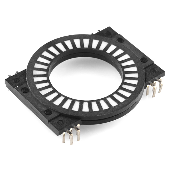
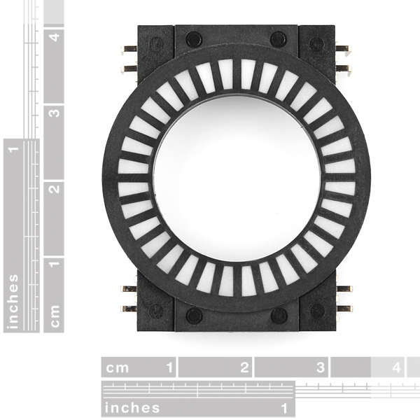
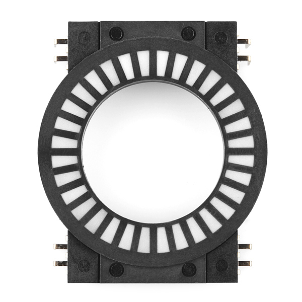
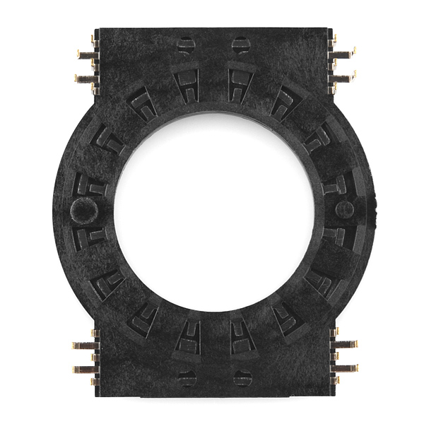
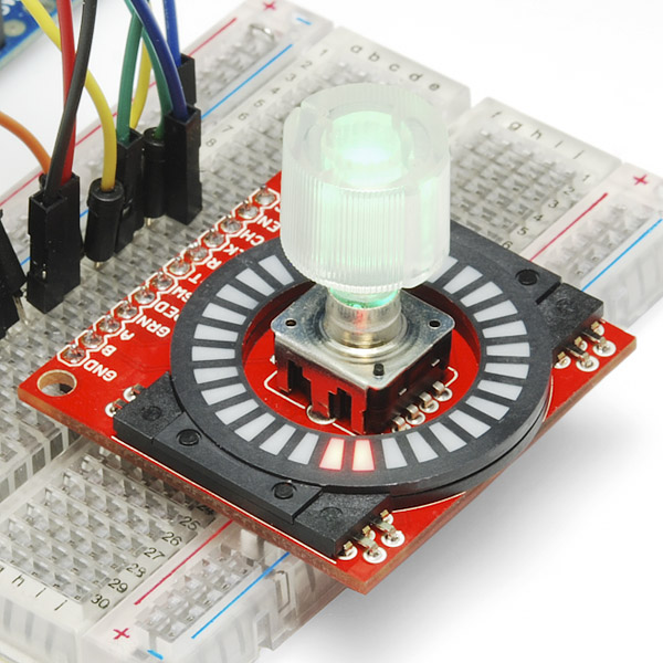
These circular LED displays are a lot of fun. Essentially, these are what you would get if you could 'wrap' one of our LED bargraphs around a circle. They consist of 16 red LEDs arranged so that each quarter of the circle has a common ground and four anode pins, resulting in 20 pins total on the device. Because they're simply a bunch of cleverly packaged LEDs, they're just as easy to use as our LED bargraphs. These are great for indicating the position of a rotary encoder!
- 16 Red LEDs
- Max Forward Voltage: 2.4V
- Dominant Wavelength: 624nm
- Continuous Forward Current: 25mA
Circular LED Bargraphs - Red Product Help and Resources
Core Skill: Electrical Prototyping
If it requires power, you need to know how much, what all the pins do, and how to hook it up. You may need to reference datasheets, schematics, and know the ins and outs of electronics.
Skill Level: Competent - You will be required to reference a datasheet or schematic to know how to use a component. Your knowledge of a datasheet will only require basic features like power requirements, pinouts, or communications type. Also, you may need a power supply that?s greater than 12V or more than 1A worth of current.
See all skill levels
Comments
Looking for answers to technical questions?
We welcome your comments and suggestions below. However, if you are looking for solutions to technical questions please see our Technical Assistance page.
Customer Reviews
No reviews yet.

I saw the board too. Looks pretty sweet. After doing an extensive Google search I ran across this,
https://www.sparkfun.com/products/retired/10704
I'm looking at the pictures for the Circular LED Bargraph and one of the pictures shows a circuit board wth a circular bargraph and a rotory encoder...this would be perfect for testing the bargraph...does anyone know what this is and if it is available for buying...
Finally had a play with these before having to hand them over tomorrow.
A piece of good news - for those who care - the diffuser can easily be removed by clipping the 4 little pins.. it's not glued on in addition to that. That leaves you with 16 little cavities in sharp trapezoid shapes with tiny LED dies in there that will light up like little points. They don't look all that well-protected, so if you do remove the diffuser, you may wish to replace it with your own.
For those wondering why you'd want to remove the segmented diffuser in the first place - for our purposes, we needed 16 bars, exactly the number of LEDs. However, the diffuser makes it seem as though there might be 32. Don't want to confuse people. Or maybe you want to turn it into a smooth diffuser. Regardless, it's easily done.
The rest of the package appears pretty well stuck together.
A breakout board with this and an I2C controller would be really nice. TI makes a 59116 chip that I'm fiddling with, 16 PWM-dimmable LED outs, I2C in.
--Joe
Unfortunately that won't work as the bargraph is common cathode, and that driver will only work with common anode. If anyone knows of an individually dimmable LED driver please reply.
ok, who else had the first thought "iron man arc reactor" :D
Also: by the image and count, each of the 16 leds lights 2 of the lenses, for a total of 32 lenses. good thing to note :) Final note: the 25ma is for ONE led, not all 16 which would push 400ma in total.
""ok, who else had the first thought "iron man arc reactor" :D ""
I did :P I already build one myself but I want a thinner one, so this could help. Too bad it's red. White or blue would be nice.
[edit] too small for an arc reactor. should be about 6 cm, this is only 3,5.
Yes, this is what surprised me. Why have 32 lenses with only 16 LEDs? Unfortunately the datasheet is relatively uninformative there, and the manufacturer's site doesn't fare much better (datasheets by request? huh.)
yes, each LED has 2 lenses. That's just how they are...
Curse that funky manufacturer!
I saw they also have a very 'X-Box' color palette version.. that explains the 4 commons, at least :)
Re: the common pins,
The 4 common pins are not one per segment (which would have made sense), but they're also not all interconnected (as per description and dimensional drawing).
Presume the following to be a schematic - [( )] - then the top-left common pin is connected to the bottom-left common pin, and TR with BR. Left and right do not connect together. So in essence, there are two common pins.
This is good news for me, I plan to try to separate them so that they are quadrant-specific grounds. That way I can drive it with the LED display driver at half the running current. Thanks for noting this!
Too bad they didn't make these in RBG
They would be horribly expensive :)
If you look above in my post the price for 16 RGB's is between $5.328 and $6.17- just would have to do a redesign on the board that all the LED's would sit on.
Looking forward to your $16 part already :)
These are pretty poorly designed. The pins don't have standard spacing to fit a bread/protoboard, and they aren't even properly sized to fit typical female leads. Soldering leads directly onto the pins is problematic because the pins are VERY fragile. I highly recommend skipping this product.
Sorry to hear you were so dissatisfied with this! Did you try using the breakout board at all? Or did you have problems with the headers specifically when connecting it with the breakout board?
Someone tell me how to right one of these up to a mini photocell or lilypad light sensor so that it roughly measures the amount of light coming in. Is it possible?
See it in Action!
I echo many comments regarding true RGB LEDs and I would suggest a board with 36 individual LEDs and a diffuser to match. With 36 addressable LEDs you could use it both for navigation (10 degree per LED) and time (3 divisions per hour) applications..
Of course a breakout board would be great!
Will the joystick fit inside the hole of the circular bargraph? As in the PlayStation 2 joystick? Or how about the PSP style thumb joystick
I wish all pins were exposed, then with just 5 outputs I could lite any one of them (20 max); 2 at a time using 50/50 multiplexing. :(
for only $10 it might be worth getting one to hack.
For anybody looking for these at a cheaper place Check here, send a request sheet http://top-up.so-buy.com/front/bin/ptlist.phtml?Category=336089
I'd buy a bunch of these if they were just a little cheaper. It's impossible to find curved or circular bargraphs anywhere. I think these are the only ones actually made. I only find data sheets for others. I'd love for someone to show me wrong.
Can anyone suggest to me a good way to get these hooked up without custom PCB layout? I can't find any connectors or protos with the proper spacing for the pins on this part. I could get the drill out, but geez. This part is proving very hard to work with... (I second the call for a breakout board for this guy)
I've had mine for a couple weeks now, but haven't been able to do anything with it since it doesn't fit into a breadboard. I'm waiting for a pin crimper to arrive in the mail so I can make female-ended jumper wires.
fwiw the lead width on these (according to datasheet and visual) is 0.8, and the pitch (on each row) is 2.6. I can't find a jumper for a lead width of 0.8 anywhere... I guess I am just going to go back to soldering the leads directly on to the part :(
Those 'pins' are much wider than standard IC pins, so be aware of that. I'm not sure if there is a standard for that particular type of pin? If I could get female jumper leads for those pins, I would do it in a second, but I don't know if they even exist... Do you have any leads on that? (pun intended)
I'm a newb, but if I'm reading the dimensional drawing correctly, then the pins won't fit down into a breadboard, right? (They appear to be on a 0.1"/2.5mm grid one way, but half appear to be offset from that grid in the other direction.) As insanely cool as this will be in a project I'm working on, I really have to hold off on ordering these (and the rotary encoders to go with them) until the breakout board is available. bummer.
That is correct - though honestly, a couple of female-male pinned wires would do you over in a pinch :)
If only the manufacturer went with 12 LED's instead of 16. These would've been ideal for custom wristwatches and other time displays.
Hell, even 10 would've been better for decimal counters. I guess they were thinking of HEX IC's with 4 data lines when designing them.
This is the coolest thing ever. In my next order for sure.
For those looking for an Eagle library part for this, there's one in the sparkfun eagle library, and an alternative in http://forum.sparkfun.com/viewtopic.php?f=14&t=29476
Any chance of making one about the same size as that softpot? I'll probably make one by scratch in the next few weeks. I want to use the softpot as a volume control but I want it to light up to show the level.
Little chance of that. These aren't made by Sparkfun, but by Top-Up Industry Corp as part of their rotary encoders line of products;
http://top-up.so-buy.com/front/bin/cglist.phtml?Category=325007
I guess if you could convince them that there's a market of, say, 10,000 units...
That said, it looks like this display should fit just about* inside the inner diameter of the softpot's active area. Presuming that outer area is indeed wasted space just for the adhesive, that can be cut away and *if needed, scrape the plastic from the circular display some.
http://imgur.com/Zl5CB
Of course, if you wanted it along the outside, you'll definitely have to roll your own :)
when will the breakout be available? I'm about to place an order but would wait for it in the same shipment.
wow they are kinda expensive. when you fist put them up they would like 4$ for that price i would buy but im afraid 10$ for a round thing of leds is to much mayb 13$ for the break out board with everything on but
Really? I don't find them expensive at all.
I agree that the price seems high, but keep in mind that their production volume is probably fairly low - there's just not that much demand for circular indicators except in maybe studio equipment.
Looks like SFE bought 1,000 units to get as good a price as they could without going broke, themselves ;)
It's also still cheaper than the existing rotary encoder/display breakout board ( http://www.sparkfun.com/products/10408 ), which has fewer LEDs that don't go all the way around - but does provide an SPI handling chip.
It's definitely cheaper to roll your own if you've got the equipment; blank PCB, laser printer, etchant, SMD components, diffusing plastic sheet, overhead projector sheets for laser printers to print a mask on (if you can't print directly onto the diffusing sheet) and any random bits and pieces to block lighting from adjacent cells or alternatively a 3D printer job.
That takes a good bit of time, though, and I'm not sure how much cheaper that would actually be :)
Wow - years ago, I begged Nathan to find a source for the ultra-cool control knobs on the Avid System 5 Audio Console.
He finally came through! I wish they'd been available for my last knob-based project - I may have to re-do it just to take advantage of the the new knobs.
cool
They could have easily multiplexed the LEDs, 4 sets of 4 would have resulted in 8 pins total.
The reason they didn't is because the product also comes in a 4-color variation. You generally don't want to multiplex LEDs with different Vf's.
It would not be much different than the multicolored LED matrices (I concede they have separate anodes). Those are generally operated via PWM (ie MAX72xx). You have a bit more wiggle room in Vf with PWM.
Also, with 8 pins, you could drive two of these with a single MAX72xx.
OR 1- NXP’s PCA9635PW
BTW- like your thinking Decep
I'm envisioning a compass sensor in the center with these LEDs pointing north.
16 player electronic spin-the-bottle?
It's too bad that the arrangement of these LEDs make it bad for a clock.
Awesome!
We'd been looking for circular bargraphs, couldn't find any available for cheap - we ended up making our own. This product actually wouldn't fit our needs, but I can see our techs using these for debugging, platform demonstrations, etc. Much more portable than our full-size displays.
Time to make another order at SFE.
Just one question... where's the 32-LED version? ;)
I AMEN the 32- Version, and maybe a version that LGB too...
nice you mean a 96 led version? ok, but forget about $9,95... anyways I would hack it
Well, 32 LED Version would be for Red/Green (2x16) if I understood things right. Wouldn't it be 48 (3x16) if it was Red/Blue/Green? They are using 4 common pins connected to all the Cathodes. So, they could have had one common for each of the three colors. Then all you have to do is Multiplex for each LED. If you really want to up the ante use NXP’s PCA9635PW to control 16 LED’s using I2C. Then all you’re playing with is 4 wires (VCC, GND, SsA, SLC). Cool thing about the PCA9635PW is that they are addressable.
YES, I agree then it would not be just $9.
Right now if you look at Digi-Key Part Number CLV1A-FKB-CJ1M1F1BB7R4S3CT-ND- that’s just one of many RGB LEDs and let say you pick up 2000 RGB leds, the unit price is around $.333 cents. That means for around $5.328 you can have your 16 RGB LEDs. If you were to use Digi-Key Part Number 67-2125-2-ND- you are looking at $6.17 for all 16 LEDs.
Why would I consider RGB important for a display like this? Well, first if you PWM this you can have any color you want. So they charge let’s say $16 for this Circular LED Bargraphs. How many Illuminated Rotary Encoders are you going to have for a project? One, two, three, four?
Then there is the BLING thing, you could have the display cycle though the 16,777,216 colors (256x256x256 using three PCA9635; one for each color). The other side of the coin is they only have to make one type of Circular LED Bargraphs to fit everybody’s needs. Considering I have seen Rotary Encoders that go for $117 on either Mouser or DigiKey, this display is cheap.
As for making something like a 36 lenses display (I could see this used for something like a compass or part of a clock) or 32 lenses display (things that use multiple of 2), I could see either of these sizes useful too. But I would not make them in just one color. I would make them with RGB LEDs.
I know I said that totally backwards about the 32 –Version, I am just thinking about how you could use the same layout inside of the package to get more colors.
The only other thing I would want changed is that the Rotary Encoders - Illuminated really needs to be in RGB too. I don't understand why they didn't put all the switches on one side and that would have opened up one pin for blue on the other side, making it RGB.
Enough people are drooling over these, it seems like a matter of time before we see one with 32 RGB LED's :)
What's that breakout board it's attached to in the last snapshot, with the rotary encoder?
Just a prototype :-)
A prototype that needs to get finished pronto! :p
check the related products below. we have it for sale.
So when is the breakout board coming out?
breakout, breakout, breakout!