SparkFun Voice Recorder Breakout - ISD1932
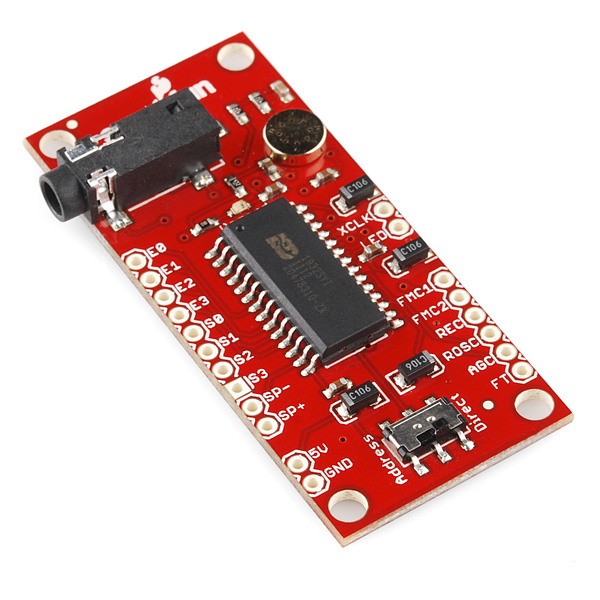
This is a breakout board for the ISD1932, a multiple-message record/playback device. This single chip can record up to 64 seconds worth of voice messages. Microphone inputs and speaker outputs are all handled by the ISD1932.
A switch is connected to allow selection of the ISD1932's operating mode - address trigger or direct trigger. You must cycle the power after switching the mode. An LED is also populated on the board and will illuminate when the device is recording. An external resistor is necessary to select the record duration and sampling frequency, which can range from 21.2 - 64 seconds (4-12kHz sampling frequency).
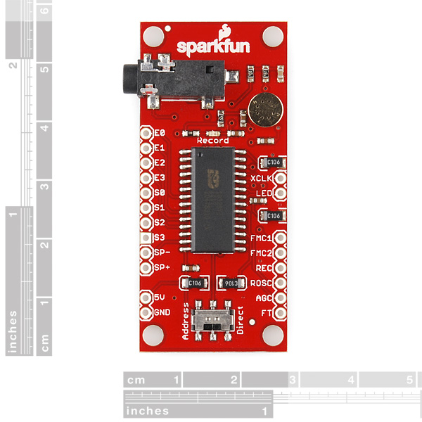
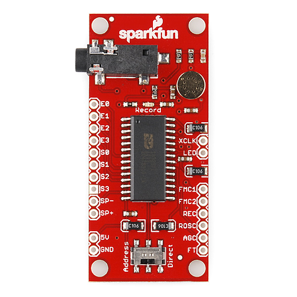
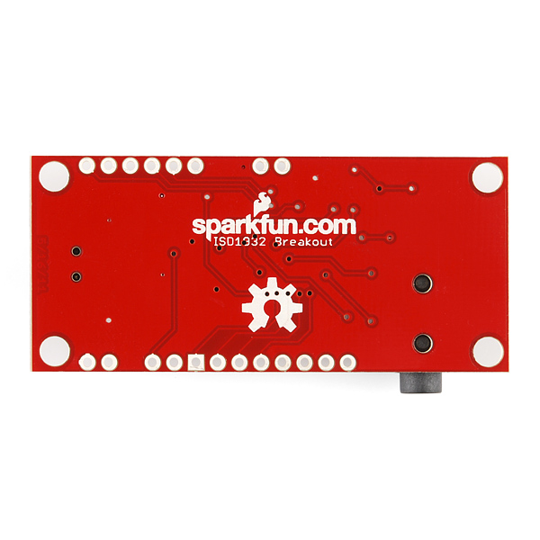
The board breaks out all pins of the ISD1932 to 0.1" spaced headers. This product comes as shown in the pictures with filtering capacitors, an LED, mode selecting switch and the ISD1932 IC. The new version of this board also includes a microphone and a 3.5mm audio jack.
- Operating mode selector switch
- 2.4V to 5VDC supply voltage
- LED indicates if the board is recording
- Record up to 64 seconds of audio
- All pins of the ISD1932 broken out to 0.1" headers
- Breadboard friendly
- [Schematic](http://cdn.sparkfun.com/datasheets/BreakoutBoards/ISD1932 Breakout-v21.pdf)
- [Eagle Files](http://cdn.sparkfun.com/datasheets/BreakoutBoards/ISD1932 Breakout-v21.zip)
- Datasheet (ISD1932)
- Sample Recording
- GitHub
SparkFun Voice Recorder Breakout - ISD1932 Product Help and Resources
Core Skill: Soldering
This skill defines how difficult the soldering is on a particular product. It might be a couple simple solder joints, or require special reflow tools.
Skill Level: Noob - Some basic soldering is required, but it is limited to a just a few pins, basic through-hole soldering, and couple (if any) polarized components. A basic soldering iron is all you should need.
See all skill levels
Core Skill: Programming
If a board needs code or communicates somehow, you're going to need to know how to program or interface with it. The programming skill is all about communication and code.
Skill Level: Rookie - You will need a better fundamental understand of what code is, and how it works. You will be using beginner-level software and development tools like Arduino. You will be dealing directly with code, but numerous examples and libraries are available. Sensors or shields will communicate with serial or TTL.
See all skill levels
Core Skill: Electrical Prototyping
If it requires power, you need to know how much, what all the pins do, and how to hook it up. You may need to reference datasheets, schematics, and know the ins and outs of electronics.
Skill Level: Rookie - You may be required to know a bit more about the component, such as orientation, or how to hook it up, in addition to power requirements. You will need to understand polarized components.
See all skill levels
Comments
Looking for answers to technical questions?
We welcome your comments and suggestions below. However, if you are looking for solutions to technical questions please see our Technical Assistance page.
Customer Reviews
5 out of 5
Based on 1 ratings:
1 of 1 found this helpful:
It did everything I needed
I used this, along with a PicAxe 28X2 module, to build a "magic eight ball", that answers questions by randomly selecting from eight recorded voice messages. The board has a mic built in and an audio jack for external speakers, which make it easier to use. The documentation (from the chip manufacturer) was complete and not too difficult. Some of the wording in it almost seemed to be translated but I was able to get what I needed.
The audio quality is excellent.


This board was excellent for trying to help my brother who has aphasia. Please see the short video clip. Wish I had recorded the audio better as this board produces excellent audio; I choose the configuration resistor for maximum fidelity.
I'm surprised that there seems to be nothing on the market for people with expressive aphasia. It would be easy to make a box with 8 short messages.
Awesome work! Wish the best for you and your brother!
can this be used to record circularly? IOW so you are always recording the last 30 seconds and can play back the 'last 30 seconds' at any time? or is it strictly "record" then "playback"?
I was wondering if we can get the audio file that we recorded and save it onto computer if we connect this with arduino uno.
I want to use the sound module without a controller -- can I get the audio to loop? I need to have it run constantly. Thanks joel
This is possible by holding the PlayL pin low and setting the appropriate addresses for the audio.
Thanks to a lot of the comments here, I used this in my Halloween project this year. The complete writeup, including wiring diagram is on my blog:http://baldwisdom.com/electrify-your-halloween-making-things-scream/ I also started a simple arduino library for it: https://github.com/osbock/ISD-library
There is a tutorial online on using the ISD1932 breakout board right here => http://ianlangelectronic.webeden.co.uk/#/voice-recorder/4562321245
I have this board working where I can record a message (@ 3.5v, direct mode, single message, 150k ohm Rosc). I can only record if the line out jack is not connected (no biggie, but might help others looking at this board). I can start & stop play, no problem. But the 1932 spec sheet says feed-through only for single ended audio! The board had a differential mic glued down. I can't get feed-through to work. Is it because the differential mic is present? Has anyone gotten feed-through to work with this board? Do I need to lift the capacitors and solder down a single ended mic to get feed-through to work? If so, this should still allow muxing between the recorded audio and the single ended mic? So close to finishing my project! Any help is very much appreciated! :-)
Sorry, this is actually a single-ended mic. A closer look at the schematic shows that the "negative" leg of the mic is tied to "LED" which is an output of the 1932. "LED" is active low so when recording (the red LED is lit), the mic operates like a single-ended mic. But when not recording, the mic is ineffective because "LED" is driving high...which is why it doesn't work in feedthrough mode.
Has anyone created a wiring diagram to make this board work? Perhaps a description of the pinout from the board? I'm hoping to create a voice module with best quality audio, one message, of 20 seconds duration. Thanks! John
We ordered there and were so sad that we could not find an elegant way to solder our own external mic. May I suggest a couple of through-hole points on the mic-connections, coupled with designated places to cut the traces for the built-in mic?
I have used this chip a few times and it does have the ability to sound much cleaner than the sample recording here. I am not sure what the sample frequency is that the sample is, but a single resistor change with this part can increase or decrease the frequency... just look at the datasheet for the chip. Also, the LED pin should be connected to the microphone input, it is a technique they use to disable the microphone when its not in record mode.
Has anyone gotten this to work? I have one, but I can't seem to get it to record. Feedthrough mode doesn't work (tying it to low doesn't output the audio to the speakers). And the LED pin is always on.
Do you have any of the old ones left? I built some circuits around the pinout from that one, and need at least 2 more of the old-style one...
On the schematic, it looks like part of the mic circuit is tied to the LED pin? Is this intended?
That recording sounds pretty terrible. I'm sure it's possible to get better samples, but wow.
I have the previous version of this one and it sounds very clean (I have been recording directly from MP3 player's headphone output).