Heatsink and Fan - 70mm
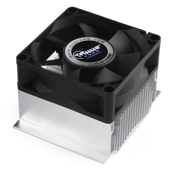
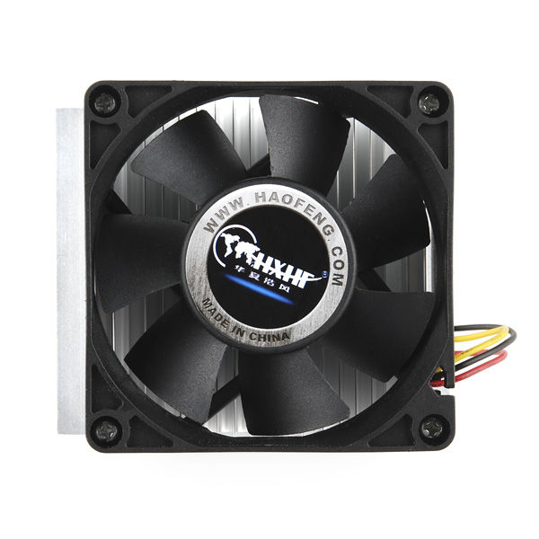
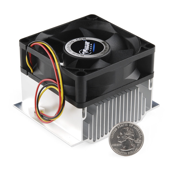
This heatsink and fan combo was originally designed to work with an Intel Pentium 4 478 on a computer motherboard, but we find it works well in combination with our thermoelectric cooler. The 70mm fan runs at 3500 RPM at 12V. It has an RPM signal wire for sensing fan speed as well as two connectors for power.
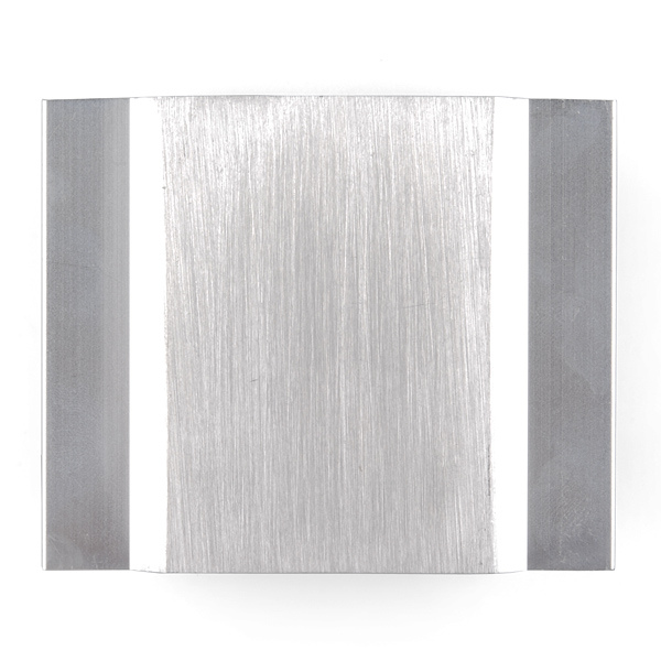
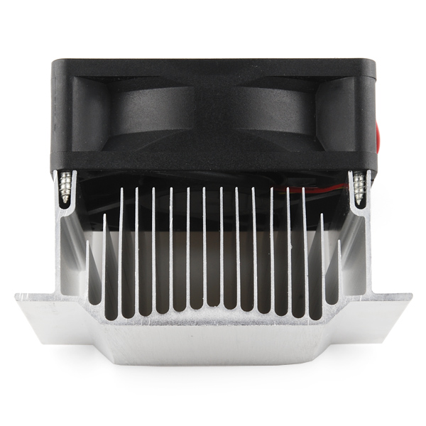
The heatsink measures 80×69mm at the base and is 35mm tall. Overall (with the height of the fan) the combo is 60mm tall. The fan itself is about 25mm tall.
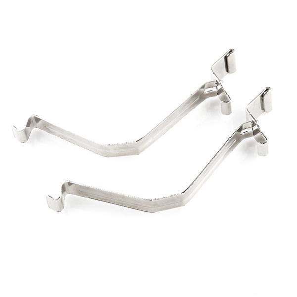
Note: This comes with some mounting hardware that we don't know how to use
- 12VDC fan
- 28.6 dB fan noise
- 32.1CFM
- 3500 RPM fan speed
Heatsink and Fan - 70mm Product Help and Resources
Core Skill: DIY
Whether it's for assembling a kit, hacking an enclosure, or creating your own parts; the DIY skill is all about knowing how to use tools and the techniques associated with them.
Skill Level: Noob - Basic assembly is required. You may need to provide your own basic tools like a screwdriver, hammer or scissors. Power tools or custom parts are not required. Instructions will be included and easy to follow. Sewing may be required, but only with included patterns.
See all skill levels
Core Skill: Electrical Prototyping
If it requires power, you need to know how much, what all the pins do, and how to hook it up. You may need to reference datasheets, schematics, and know the ins and outs of electronics.
Skill Level: Rookie - You may be required to know a bit more about the component, such as orientation, or how to hook it up, in addition to power requirements. You will need to understand polarized components.
See all skill levels
Comments
Looking for answers to technical questions?
We welcome your comments and suggestions below. However, if you are looking for solutions to technical questions please see our Technical Assistance page.
Customer Reviews
No reviews yet.

Any chance we can get rulers added to those pictures, or ideally some outermost dimensions?
Need to know if this will fit in a given space or not, and the 80x69mm dimension of the bottom face is great and all, but it clearly gets wider than that.
Gah, I want one!
Is there a max current rating for this? Does it matter?
I purchased two of these fans to use with some 40mm square TECs. I noticed the bottom of each unit was ever so slightly concave. As a result, I was not able to get adequate thermal contact between the TECs and the heat sinks using the thermal tape listed below. If you plan to use these heat sinks, order the thermal grease.
Is the red wire positive, the yellow wire RPM, and the black wire negative?
That is standard for computer muffin fans, yes.
the retaining clips hook under a retaining loop mounted to the board below, and the center of the V presses down on the flat flanges on the sides of the heatsink. the swivelled hinge hooks under a matching loop., to provide sufficient spring pressure to keep the sink solidly in place. Perhaps someone at SFE could design a set of custon retaining hoops for this, because there already exist "jumper stirrups" which are used for a spring-held Northbridge on a PC motherboard. these consist of a 3x 0.1" header, and a radius-bent metal bar through the outer two holes in the header strip
barely visible at the very front here http://techreport.com/r.x/p4-sdram/845-northbridge.jpg
I'd love to see SparkFun characterize their heatsinks and heatsink/fan combos by providing a thermal resistance value for each of them. That would really help people who are trying to come up with designs that you can just get right the first time without too much experimentation.
How about turning this into a solderpaster cooler?
offhand, those look like AMD CPU clips....