GPS Shield Retail Kit
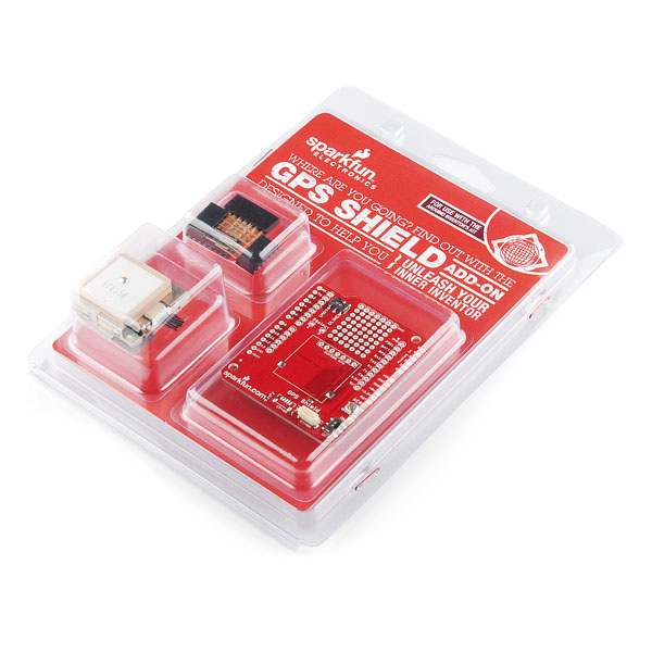
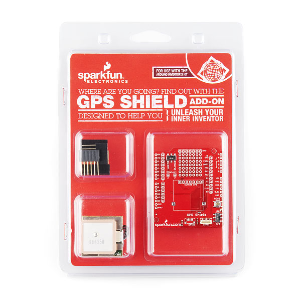
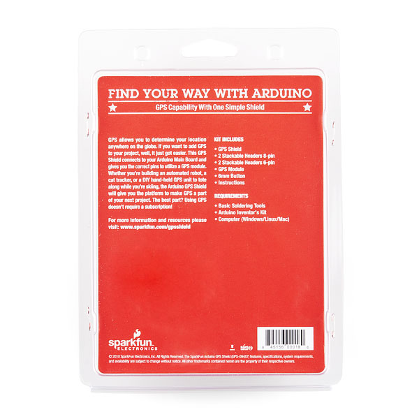
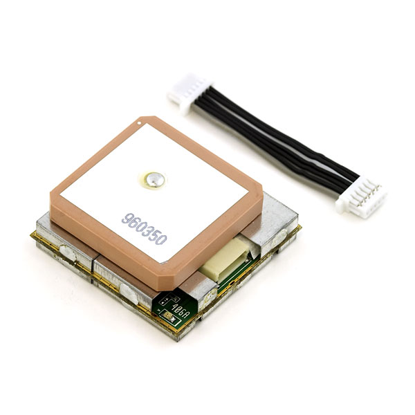
This is the same product as the GPS Shield, but also includes an EM406 GPS receiver and headers. The difference is, this version comes in fancy clamshell packaging meant for our distributors. Regular customers are welcome to order, but we want to limit the amount of extra packaging finding its way into the trash heap. A GPS quickstart guide and a GPS Shield Assembly Guide are available for this product.
Adding GPS to your Arduino has never been easier. Multiple GPS receivers attach easily to the shield, and with the example sketch (check below), you will be able to locate your exact position within a few meters. Here's where we are. GPS also gives you amazingly accurate time!
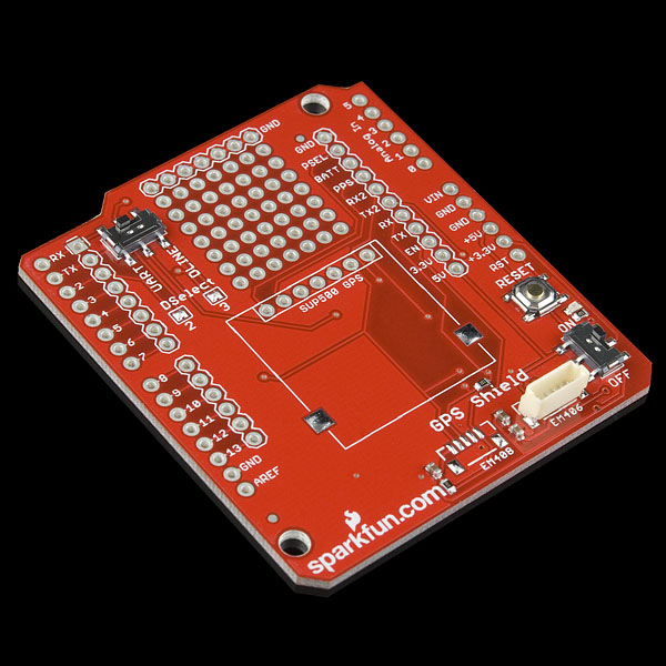
A connector for the popular EM-406 GPS receiver is populated on the board, and footprints for EM-408 and EB-85A connectors are also made available (connectors are not included and can be found below in the related items). There is also a spot for the UP501 GPS module. The regular GPS pins (RX, TX, PPS, etc.) are also broken out to a 10-pin 0.1" pitch header, and a small protoyping area is also provided.
The DLINE/UART switch switches the GPS module's input/output between Arduino's standard TX/RX pins or any digital pins on the Arduino (default setting uses pins 3 and 2 connected to TX and RX, respectively). The DLINE/UART switch must be set to DLINE in order to upload code through the Arduino IDE.
The shield also includes the footprint for a 12mm coin cell battery holder to provide battery backup to the optional EB-85A GPS module.An ON/OFF switch is included which controls power to the GPS module. Additionally, the Arduino reset switch is also brought out.
**Replaces: **RTL-10346
- GPS Shield
- EM-406 GPS Module
- EM-406 Interface Cable
- Set of Stackable Headers
- EM-406 connector populated
- EM-408 and EB-85A connector footprints provided and connected for optional use
- UP501 connector and footprint
- Coin cell battery socket footprint provided and connected for optional battery backup of EB-85A GPS module
- Standard Arduino sized shield
- Prototyping area
- GPS serial and PPS signals broken out to a 0.1" header for additional device connections
- Arduino reset button
- DLINE/UART switch controls serial communications
- ON/OFF switch controls power to GPS module
GPS Shield Retail Kit Product Help and Resources
GPS Shield Hookup Guide
March 9, 2015
This tutorial shows how to get started with the SparkFun GPS Shield and read and parse NMEA data with a common GPS receiver.
Core Skill: Soldering
This skill defines how difficult the soldering is on a particular product. It might be a couple simple solder joints, or require special reflow tools.
Skill Level: Rookie - The number of pins increases, and you will have to determine polarity of components and some of the components might be a bit trickier or close together. You might need solder wick or flux.
See all skill levels
Core Skill: Electrical Prototyping
If it requires power, you need to know how much, what all the pins do, and how to hook it up. You may need to reference datasheets, schematics, and know the ins and outs of electronics.
Skill Level: Rookie - You may be required to know a bit more about the component, such as orientation, or how to hook it up, in addition to power requirements. You will need to understand polarized components.
See all skill levels
Comments
Looking for answers to technical questions?
We welcome your comments and suggestions below. However, if you are looking for solutions to technical questions please see our Technical Assistance page.
Customer Reviews
No reviews yet.

I have Arduino GSM shield mounted on Arduino uno. Can I stack this GPS shield above Arduino GSM shield ? Will there be any pin configuration problem ?
In GSM Shield hardware pin's configuraton GSM Shield
If there is any problem, how it can be solved.
I have had some problems with this GPS. I can get the coordinates and other information but sometimes after I switch off and on again (or after upload a new code to Arduino), it takes forever to get the signal. Sometimes just disconnecting from the power and connecting is enough but sometimes takes 1-2 hours and that drives me crazy.
Is someone having the same problem or know how to solve that?
Thanks
when it will be in stocks again?
I purchased many of these components induividually, and i have been running into a problem. The GPS i bought is an EM406, and appears to be the same one as the one included in this kit. However, I have been told elsewhere i have to make sure my GPS isnt outputting in RS 232 format instead of serial. I dont exactly know what this means, i know there is a RS232 to Serial shifter, but im confused. Anyone have any suggestions? I am using an arduino UNO (or Yun I have both), the GPS shield shown here, and this (https://www.sparkfun.com/products/465) GPS. I dont know why i am having such huge issues.
Is this compatible with the Arduino Due? I assume so but just want to make sure there are no issues due to the Due being 3.3v based?
So say I have a 7inch touch screen tft lcd hooked up to an Arduino Due... Is there any way I can have maps and create a full navigation system. I am turbocharging a big car, going to have tons of power around 600, I want a screen in the dash that can control servos to regulate boost pressures and everything, I also want the stereo done on the Due (Easy can be done in minutes), and I want to add a possible navigation system. Anyone done it with maps? Thanks
Can anyone help me this working? My serial monitor is outputting 0.N²þ and nothing else. Is it possible I soldered it wrong? What might be the issue?
I think we got this question answered already, but for anyone else running into the same issue, please double check that all your baud rates match up correctly, and your connections are good, withe proper power to the module.
Does anyone have anything to say about how the "course" readings given by this module are? The example sketch above and examples with the TinyGPS library make use of course() and f_course() functions. How reliable are these values, and does anyone know how they are determined? Is their a digital compass within the unit or is it extrapolating recent GPS data?
Although some GPS modules include a magnetic compass, this one does not. Thus it comes up with course and speed by looking at the difference between the current fix and the last fix. (The device is probably smoothing between several fixes, but essentially that's what's happening). Course and speed will be more accurate the faster one is going (which gives a greater distance between fixes), and if you're standing still, the course will be effectively random, but the speed should accurately be near zero. Note that it's the GPS module itself that does this; TinyGPS just pulls those values out of the GPS data.
Has anyone had any luck on the Mega? I've tried this, http://arduino.cc/forum/index.php/topic,27737.0.html, desoldered the 2 jumpers and using UART 3 (pins 14 & 15) but only get 3 digit serial outputs, e.g. - 245, and NewSoftSerial and TinyGPS library functions are not outputting diddly...
Works very well with a few modifications to Aaron's sketch. Thank you Sparkfun for not only providing a good product, but some tools to help us newbies out. I look forward to purchasing more shields.
Got the shield, soldered the headers on, had a GPS fix in just a few minutes. Couldn't be happier.
hey...
Fixed.
Seems to be a copy/paste of a similar product (without the packaging) description. The picture of the packaging shows the GPS chip clearly (bottom left).
Can you connect the 66 Channel LS20031 GPS 10Hz Receiver (sku: GPS-08975)to this shield?