×
SparkFun will be closed Nov. 28th and Nov. 29th in observance of Thanksgiving. Any orders qualifying for same day shipping placed after 2:00 p.m. MST on Wednesday, Nov 27th will be processed on Monday, Dec 1st. Wishing you a safe and happy holiday weekend from all of us at SparkFun!
Color LCD - Breakout Board
Replacement: None. We are no longer carrying this LCD breakout in our catalog. This page is for reference only.
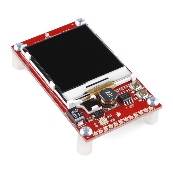
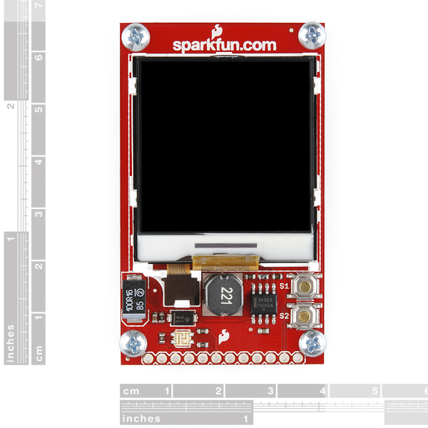
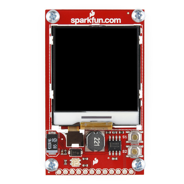
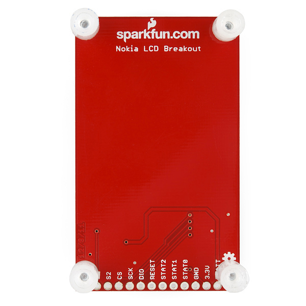
Created for the Sinister 7 Tutorial, this breakout board for the popular Nokia 6100 Knock-off color LCD has an improved backlight driver circuit (boosts to 7V) , plus we give you a tri-color status LED and 2 pushbuttons, all accessed through one 12-pin 0.1" spaced header. Vbat and the 3.3V input can be driven from the same regulated 3.3V source, but the device will draw more current than if the Vbat input was driven from a higher source voltage. For an estimate of the current draw for a given input voltage, refer to the chart on the schematic file below.
This breakout is set up for serial communication to the display and comes with the Nokia 6100 display attached and stand-offs as photographed.
****Note:**** Pins 8 and 9 on the Nokia LCD connector will be connected with a solder bridge.
****1.5"x2.5"
****Replaces: ****LCD-08600
Color LCD - Breakout Board Product Help and Resources
Core Skill: Soldering
This skill defines how difficult the soldering is on a particular product. It might be a couple simple solder joints, or require special reflow tools.
Skill Level: Noob - Some basic soldering is required, but it is limited to a just a few pins, basic through-hole soldering, and couple (if any) polarized components. A basic soldering iron is all you should need.
See all skill levels
Core Skill: DIY
Whether it's for assembling a kit, hacking an enclosure, or creating your own parts; the DIY skill is all about knowing how to use tools and the techniques associated with them.
Skill Level: Noob - Basic assembly is required. You may need to provide your own basic tools like a screwdriver, hammer or scissors. Power tools or custom parts are not required. Instructions will be included and easy to follow. Sewing may be required, but only with included patterns.
See all skill levels
Core Skill: Programming
If a board needs code or communicates somehow, you're going to need to know how to program or interface with it. The programming skill is all about communication and code.
Skill Level: Competent - The toolchain for programming is a bit more complex and will examples may not be explicitly provided for you. You will be required to have a fundamental knowledge of programming and be required to provide your own code. You may need to modify existing libraries or code to work with your specific hardware. Sensor and hardware interfaces will be SPI or I2C.
See all skill levels
Core Skill: Electrical Prototyping
If it requires power, you need to know how much, what all the pins do, and how to hook it up. You may need to reference datasheets, schematics, and know the ins and outs of electronics.
Skill Level: Rookie - You may be required to know a bit more about the component, such as orientation, or how to hook it up, in addition to power requirements. You will need to understand polarized components.
See all skill levels
Comments
Looking for answers to technical questions?
We welcome your comments and suggestions below. However, if you are looking for solutions to technical questions please see our Technical Assistance page.
Customer Reviews
No reviews yet.


Thought I would post this in case it's useful. My LCD has a green PCB and it came with a red tab on the screen proctector and seems to use the Epson controller.
I ordered one of these before Christmas and had problems getting it working. The example at http://www.sparkfun.com/datasheets/LCD/SFE_lcd_driver_c.zip sort of worked - I could just see the "Hello World". However it was very washed out. After a bit of experimentation I have found that setting the first parameter of the DISPCTL command to 0x0C (instead of 0x00) fixes the problem.
I've also tried the gLCD library (https://github.com/TCWORLD/gLCD-Library.git) and that seems to work as well with the above fix.
I have problem using this with an Arduino, as the stepup voltage converter for the backlight leds generates severe ripple back to the source. Connecting the VBATT input to the +5V pin on the Arduino gives a 200 mV p-p ripple!, which severely affects ADC readings on the Arduino. Disconnecting the VBATT pin (turning the backlight off) lets the Arduino ADC work peacfully but the measured values are hard to read... ;-) Is there a good way to eliminate the ripple?
Is it possible to get the aggregate component parts and I can assemble myself????? aka: "KIT" form
Thanks
Unfortunately, we don't sell all of these parts as a kit option, but you could use the Eagle files to assemble the parts yourself if you wanted.
How would I connect an RCA input to this?
Hi to everybody! I got this product and connected it to my mbed ( LPC2368 ). I tried to run the example ( Helloworld ) posted on mbed.org, but it didn't work. The unique result I obtained was to turn on the backlight. I connected both pins Vbatt and 3v3 to the upper pin on the mbed. What's wrong with that? Should I have to connect those famous pins 8 and 9 ? Where are they on the board?
Thanks for your help.
I'm fairly new to programming and was wondering how hard it would be to take information from an accelerometer, pressure transducer (5000 psi) and a gps. Then display all that information onto a screen. Such as if no movement was detected from the accelerometer a little dot on the screen would turn red. The dot would come from the GPS. Then also the pressure displaying in psi on the screen. Would it also be possible to use an Xbee to upload all of this information to another computer?
Hello, I have a problem with mine, the screen is reversed as if I look in the mirror, is there a command for displaying correctly
thank you
Have you looked at TCWORLD's arduino library? (link in comments) It's likely that your driver mirrors things, the library should have clues on how to flip this manually if you're not intending to use the library.
TCWORLD, I cannot understand how to connect this to an arduino UNO. and make it run... I have just limited my connection to the four RESET, DATA (assume to be DIO ?), SCK and CS. What is to be connected to 3.3 V, VBATT and ground is still a mistery. Can you give me a guidance ?
A Couple questions about the backlight... What is the maximum safe voltage for vbatt? If I want to run it from a 6V sealed lead acid, which can get to ~6.5V when fully charged, is that generally safe? Can the driver disable the backlight, via sw commands when not needed? If not, would controlling VBatt with a PNP with 3.3 volt logic connected to its base?
Hello, I tried to use TCWORLD's library. I found out that breakout has a Phillip's driver through the libraries. However, the objects on the screen seem to roll out instead of just appear. Is there something wrong with my set-up or is that intended?
The screen is controlled with a Serial link, which tends to be fairly slow - This means that objects may take a couple of 10ths of a second to be drawn. I am working on a new optimised version of the library which speeds things up slightly, but there is a limit to how fast the uC can run.
How can I turn on and off the backlight? What about setting the brightness? Cant I? Or I do need an external circuit connected to the Vled input? In a battery powered system, I would like to keep it off as much as possible, and even setting the brightness low, if possible...
Any suggestion?
Thanks a lot!
Hi, the eagle files here seems to be corrupted...
This LCD is not working..it is black with only the backlight on. Wiring diagram followed as posted. When tested with an oscilloscope, the signals are being received by the board (so loose wires are not the issue). Is this a Faulty display or am I missing something. Only powered via MBED / USB connection. Emailed your customer service but received no reply after 3 days. Please advise.
I'm having the same problem. I use it with mbed and get signals with logic analyzer. Only backlight and leds work, but I can't get anything on display. Please let me know if you figure out this one....
I just ordered this display and after reading the Interface tutorial by Jim Lynch was able to get it fully functional in one night of programming. The tutorial is listed under 'documents' on this page: http://www.sparkfun.com/products/569
Make sure your code reflects the correct functions for either the Epson or Phillips LCD controller. I believe mine shipped with the Phillips controller. Great LCD, it was very easy to work with.
Doesn't seem to output display for me...
I can't really tell from any of the pictures - is it possible on this breakout board (or any others that are sold) to take off the lcd, and extend it? I would prefer to have just the plain lcd, and use an extension cable for it :P
They are really fragile connectors, so I doubt it would last long at all on an extension cable (I have already broken 2 of them making a different board for it).
That new inductor looks pretty tall - could make mounting the screen on a panel awkward?
Really the components would have been better mounted on the back of the board, with just the LCD and the push-buttons on the front, that would allow more practical mounting options.
Could you offer just the board without the display, I have the early vintage one where the voltage driver was a bit touchy.
Sorry, we only offer it with the screen.
In that case, is there any (relatively easy) way to fix the older version of the board to use the correct inductor? I have the older one too.
contact techsupport@sparkfun.com and as them. I'll let them know you're emailing. We should be able to get you an inductor if you're OK replacing it. We don't really do rework of old boards though.
Have you checked your old video cards (or other electronics junk)for a suitable inductor ? 220uH is a fairly common value. Or you could unwind a larger inductor.
Great to finally see a breakout board for this product, though that means now we need an arduino library :D
https://github.com/TCWORLD/gLCD-Library
Thats the one I wrote a few months ago :)
Thanx, I will use your Lib. But I'm using an Arduino Mega. Should I make any change?
It works fine with the Mega as is. If you plan on using high speed mode, I.e. when you create an instance of the display as: gLCD graphic(RS,CS,SCLK,SDATA,1); You may need to configure the header file to suit you pin connections. If you search the .h file for 'pin #defines' all is explained there. This speeds the display up by 10x.
Correction, search for 'Ports #defines'
Thanks you very much for the help. First, I'm going to try the example that is called "BasicFunctions". Later, I will try the speed mode.
I'm having a problem with the Print function when I use the solid background. The text can't be read.
Have you set SetBackColour(R,G,B); and SetForeColour(R,G,B);
before the print function?
Oh, I should also mention there is a new version of the library which makes using the highspeed mode easier (it automatically determines the requires port so you dont need to change the .h file).
Thanks You. Now I'm using the new version of the library with an Arduino UNO, But I'm having a problem with the speed mode. I want to use this pin setting: const char RST = 7; const char Dat = 6; const char Clk = 5; const char CS = 4; but the LCD doesn't work.
Does it work when not in highspeed mode? There shouldn't be any issue with using those pins. Also, does the test pattern work. Would you be able to open an issue on my github page and answer there rather than here.
It does work when not in high speed mode, and the test pattern also works. Actually,the only change I made was:
gLCD graphic(RST,CS,Clk,Dat,1);
gLCD graphic(RST,CS,Clk,Dat,0);
TCWORLD, I have both the old (LCD-08600) and the new (this one) Color LCD breakout board. When I use your library and load the examples using Arduino UNO board, I see it works on the old breakout board but not this breakout board. Pins and connections are correct. Do you know what I might be doing wrong? Anything new i need to do for this breakout board that didnt need to be done for the old one?
Have you tried changing the init() line at the top of the example code to load the Phillips code rather than EPSON or vice versa? How to do that is in the example. Also, have you got the latest version of the library (I fixed a bug with Phillips controllers last month).
If that doesn't work, I am not sure without some more info on what isn't working. It could be taht SF have got hold of a new type of screen? I doubt it, but if so, I ordered one of these screens in the last week, so when it arrives I can see what happens.
Yes, the display works after loading the Phillips driver code. I did not realize the new breakout out board LCD was changed from epson to phillips( green color connector to black color connector). Thank You very much for the help. Also have another question. Using your library, how can I load a picture on the screen? Any help would be appreciated. I was able to convert a picture into 12bit hex values, but not sure how to load them into LCD.
It's pot luck as to the controller really, it depends which they get. That's why my library has both, just in case. As for images, I have some code to decode and display 24bit bmp images, and also 12bit hex data. I didn't add it to the library as it was more advanced and I didn't want to clutter it. I will post the code tomorrow for you if you want it.
Yes, I would like to have the code for displaying images. Thank You.
Do you have an Arduino Mega. Sudden thought having looked at the code for bitmap decoding is that the way I did it, it uses more RAM than an Uno has, and needs an SD Card.
If you dont have a Mega, then this it is still relatively easy to do if you have 12bit hex, though it depends how you saved the 12bits. Basically, for this example, it will assume that you have saved it wastefully as a byte for R, then a byte for G, then a byte for B, and so on (and that the lower four bits of each byte contain the colour). If you have it different way, then you will need to edit the code to suit - shouldnt be too difficult.
If there are errors in that, apologies, it was taken from a larger chunk of code and simplified
I am building a project in which I receive an image ID over Xbee and I use that ID to display the appropriate image on the LCD screen. These images are being read from an SD card. Since my project involves both Xbee and SD Card, I decided to use the Wireless SD shield (http://arduino.cc/en/Main/ArduinoWirelessShield). I am seeing some strange behavior occuring with regards to the LCD. For accessing the SD card I am using the SdFat library. Since the Wireless SD shield connects the Xbee directly to pins 0,1 (RX,TX) of the Arduino Uno, I am just using Serial.print and Serial.read to send and receive data. For displaying images on the lcd I am using the latest version of the gLCD library.
The problem I am facing is as follows: First when I receive and ID through Xbee, I use that to display image on the LCD and everything works fine. However after an iteration of the loop(), when I receive another image ID, I call the DisplayLetter function but it doesnt seem to do anything on the LCD. It is very strange and I have not been able to figure out what is going on. Any help is greatly appreciated. The LCD I am using is Nokia-11062 from Sparkfun.com (http://www.sparkfun.com/products/11062)
my DisplayLetter function: void DisplayLetter(char *fileName) { int BR, BG, BB, FR, FG, FB, tempInt; SdFile myFile; if (!myFile.open(fileName, O_READ)) { sd.errorHalt("Opening file for read failed"); } graphic.SetBackColour(BR,BG,BB); graphic.SetForeColour(FR,FG,FB);
for (y = 132; y >= 0; y--){
for (x = 132; x >= 0; x--){ unsigned char val; char ch2 = (char)myFile.read(); char ch1 = (char)myFile.read(); int dig1, dig2; if(isdigit(ch1)) dig1 = ch1 - '0'; else if(ch1>='A' && ch1='a' && ch1='A' && ch2='a' && ch2
Sorry about the formatting of previous post, I am not able to post code here, form is little weird..
It sounds like there is some issue with pin connections. It may be that the wireless SD sheild uses some of the same pins as you have assigned to the display. If that is the case then the display may stop communicating. Have you checked to make sure that the display and the SD shield have no pins in common.
If this is not the problem, would you be able to open an issue thread on the library page here: https://github.com/TCWORLD/gLCD-Library/issues and post your code there. I can't really suggest anything without seeing your code.