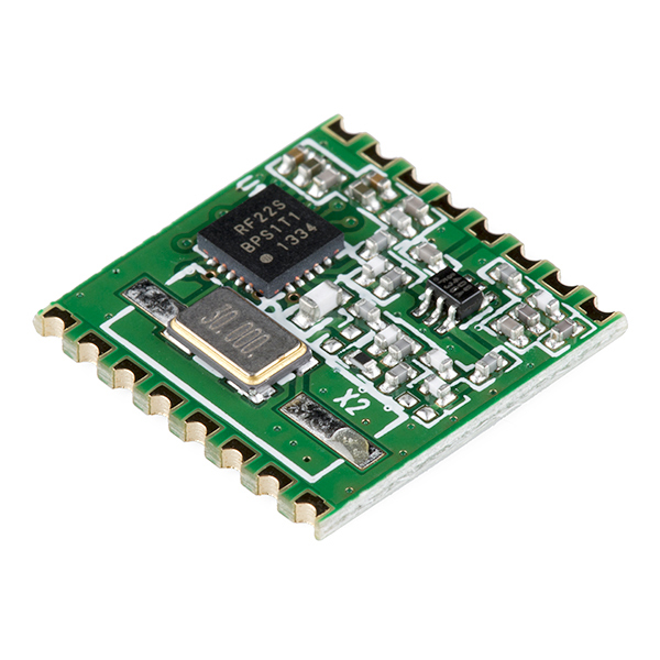
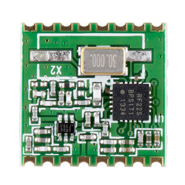
RFM22B-S2 SMD Wireless Transceiver - 915MHz
The RFM22B is a low-cost ISM FSK transceiver module which offers communication at 915MHz ISM and adjustable output power of up to +20 dBm. The wide operating voltage range of 1.8–3.6 V and low current consumption makes the RFM22B an ideal solution for battery powered applications.
Communication with the RFM22B is achieved via a standard 4-wire SPI interface. Three configurable general purpose I/Os are also available, the use of which can be tailored towards the needs of your project. A host of other features are also available including an 8-bit ADC, temperature sensor, RX and TX FIFOs, and low-battery detection. See the datasheet below for a complete description of every register and command.
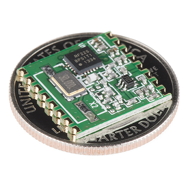
The module comes in a 16-pin, 16 x 16mm, SMD package, with pins spaced by 2mm.
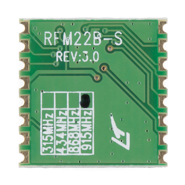
Note: These modules are 915MHz and Rev3.0.
- Frequency Range: 915MHz ISM
- Sensitivity = -121 dBm
- Output power range: +20 dBm Max
- Data Rate = 0.123 to 256 kbps
- FSK, GFSK, and OOK modulation
- Power Supply = 1.8 to 3.6 V
- Ultra low power shutdown mode
- Digital RSSI
- Wake-up timer
- Auto-frequency calibration (AFC)
- Power-on-reset (POR)
- Antenna diversity and TR switch control
- Configurable packet handler
- Preamble detector
- TX and RX 64 byte FIFOs
- Low battery detector
- Temperature sensor and 8-bit ADC
- –40 to +85 °C temperature range
- Integrated voltage regulators
- Frequency hopping capability
- On-chip crystal tuning
- 16 x 16mm (0.63 x 0.63 in)
- Datasheet
- Example Code (ATmega328)
RFM22B-S2 SMD Wireless Transceiver - 915MHz Product Help and Resources
Core Skill: Soldering
This skill defines how difficult the soldering is on a particular product. It might be a couple simple solder joints, or require special reflow tools.
Skill Level: Competent - You will encounter surface mount components and basic SMD soldering techniques are required.
See all skill levels
Core Skill: Programming
If a board needs code or communicates somehow, you're going to need to know how to program or interface with it. The programming skill is all about communication and code.
Skill Level: Competent - The toolchain for programming is a bit more complex and will examples may not be explicitly provided for you. You will be required to have a fundamental knowledge of programming and be required to provide your own code. You may need to modify existing libraries or code to work with your specific hardware. Sensor and hardware interfaces will be SPI or I2C.
See all skill levels
Core Skill: Electrical Prototyping
If it requires power, you need to know how much, what all the pins do, and how to hook it up. You may need to reference datasheets, schematics, and know the ins and outs of electronics.
Skill Level: Competent - You will be required to reference a datasheet or schematic to know how to use a component. Your knowledge of a datasheet will only require basic features like power requirements, pinouts, or communications type. Also, you may need a power supply that?s greater than 12V or more than 1A worth of current.
See all skill levels
Comments
Looking for answers to technical questions?
We welcome your comments and suggestions below. However, if you are looking for solutions to technical questions please see our Technical Assistance page.
Customer Reviews
4 out of 5
Based on 1 ratings:
1 of 1 found this helpful:
Everything worked!
I am happy with the modules. Using Radio Head libraries it worked first attempt.


To answer the gentlefolk below the rfm22b will indeed tune the full range of the device. OTOH the LC filters on the output are tuned to a specific frequency block. On the back of the device it is marked as such. The device works great but would benefit from a breakout board. I ask Sparkfun to make the same board available that is use with the 434 MHz version. They very pointedly said a big "NO". There is an Australian firm on ebay that does sell a bare BOB for this. I got two and they work great. The 33 cm band is open for this FCC part 15 device. I give this HopeRF a big 5 stars **** for this device since I cannot "review" the device.
Hi, the data sheet says the device supports from 240 MHz up to 915 MHz, why the device is announced to be working on only 915 MHz. Thx.
Hi, I have this working with an arduino uno, but I dont know how to connect this to the arduino pro micro. Especially teh NIRQ wire.....Please help me!
Serious noob question: How am I supposed to connect this to anything? I've soldered headers onto bob's and attached them to breadboards but the 2mm spacing on these prevents this. The shape of the 2mm connectors seems to be meant to connect to something specific. I'd like to attach this to a breadboard or some other type of prototyping environment but don't know how. Should I just solder wires with pins to the 2mm connectors?
Noob question: Can you "bind" this transceiver with another one so that other connections will not interfere or interrupt like an rc plane?
If this transceiver was on the same frequency range (915Mhz), could it communicate with the RFM12B with little or no differencre from communicating with it's "own kind" - or vise versa?
I am wondering because I have some sensors in a sensor network that could use the shorter range rfm12b, but others that need the longer range rfm22b (Which is twice as expensive and something that I would like to avoid using on every single board if possible)
If anyone can help / point me in the right direction, Thanks
Comparing the two datasheets, it seems that they may work together. The RFM22B will need to be in FSK modulation mode. Both will need to be on the same carrier frequency, have the same frequency deviation, and same bit rate. I have purchased both modules and I hope to test this out this weekend.
Honestly though, the RFM22B is so much more flexible and totally worth the extra few dollars, in my opinion; it will save you a headache to just get the RFM22B.
Ah, Thanks for the tip. It will probably be simpler to design just a RFM22 version of the boards as well as the RFM12 Band RFM22 have different footprints. Unfortunately this means these modules are too expensive for me to purchase from Sparkfun. Fortunately they are available other places for around $6 - Just search for "RFM22" on Google or Ebay
Anyone know if these will detect the presence/absence of a 915Mhz carrier? If so, then you have my full attention because that's the transmission mode used by my electrical meter. It would be real nice to monitor power usage wirelessly, but I haven't been able to find anything handling carrier/no carrier transmission other than possibly GNU Radio. Seems like everything in that band is FSK.
Yes! OOK [On-Off Keying], which is one of the three modulation modes this module uses, is a type of amplitude-shift keying modulation which does exactly what you want it to do.
Wonder if you can take a strip of breakaway headers pull every other one and solder them on with those divots and make it look nice while at it?
I can tell you that it is possible... it doesn't look particularly nice, though. I did this on a few of the 434 MHz transceivers so they were nice and 0.1" spaced, but in all honesty, it was ugly and made the transceiver stand about .5" off a breadboard. It seemed to work better than soldering jumper wires to each pad, but it's far better to use a BoB or design your own pcb with the correct spacing.
Let me know if you want photos of my attempt on the 434 MHz module.
Has any kind of real life range testing been done? Would be nice to know how far these could really go.
Lots of variables play into the answer to your question (antenna type, obstructions, etc.). I can only speak to the 434 MHz model, however, which I was able to get about 200 meters in open air. What might interest you, if you need more range, is the RFM69 series. Felix at LowPowerLab.com claims to have achieved 250m with the standard RFM69W, but pushed the high powered version to +400 meters. http://lowpowerlab.com/blog/2013/06/20/rfm69-library/
Again, YMMV, so err on the side of caution if a wireless link is crucial in your project.
Nice! Is the range effected in any way?
If you are referring to the 915 MHz freq. vs 434 MHz, chances are that the range and penetration will suffer slightly due to the higher frequency. The difference may not be noticeable if you use this in an open-air environment, but generally, higher frequencies are reflected more easily than low ones and require more power to cover the same area as a transmitter with a lower frequency.