SparkFun EL Sequencer
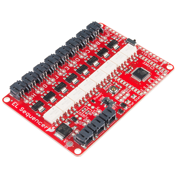
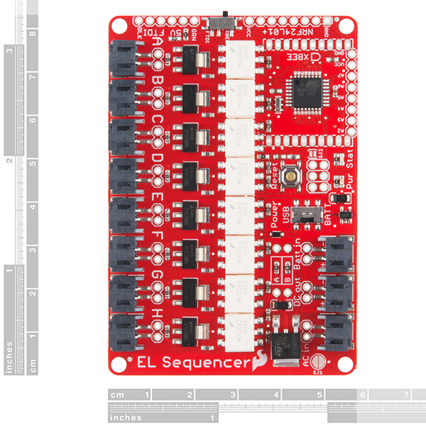
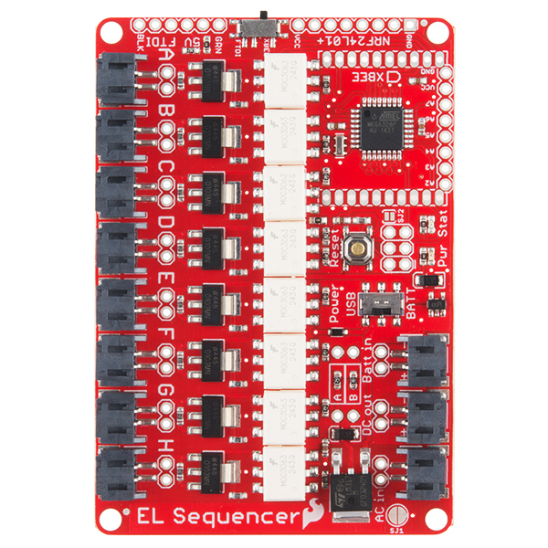
The SparkFun EL Sequencer is a board that contains an Arduino-compatible microcontroller, and circuitry for controlling up to eight strands of electroluminescent wire. EL wire is flexible plastic cord that glows brightly when high-voltage AC is applied to it. It's available in numerous colors (see the related products below), runs cool, and requires very little current, but can be difficult to work with because of the high-voltage requirements. The EL Sequencer can safely switch high-voltage AC on and off, allowing you to easily create animated displays or whatever else your imagination can come up with.
In addition to this board, you will need an inverter (a component that generates the high-voltage AC needed by EL wire), EL wire/tape/panels, and a 5V FTDI BOB or cable to load your own programs. The board also has headers for XBee and NRF24L01+ radio modules for wireless projects. SparkFun carries two inverters, a 3V-input version that can drive a few feet of EL wire, and a 12V-input version capable of driving dozens of feet of EL wire. Choose the one appropriate to your power source and driving requirements. The EL Sequencer possesses zero-crossing optoisolated triacs for noise-free operation and full isolation between the AC and DC sides, and includes a 1.5A adjustable linear regulator to supply regulated DC to an external inverter (not included).
Nate has used EL wire to make amazing interactive costumes; check out his Heartbeat Straitjacket and demo video.
Note: We have fixed the silkscreen error on this board; the FTDI "black" and "green" labels have been fixed.
- ATmega 328p running at 8MHz, with Arduino bootloader
- Eight opto-isolated, zero-crossing EL control channels
- Headers for XBee and NRF24L01+ for optional wireless control
- No library needed - control is as easy as turning a LED on and off
- Integrated 1.5A linear regulator (LM317) to supply regulated DC power to external inverter
- Linear regulator preset to 3.3V, but can be changed via PTH resistors, or bypassed entirely
- Can be powered by a 3.7V Lipo battery (using 3V inverter), or an external 3.3V to 16V supply (using 3V or 12V inverter)
- 5V FTDI BOB or cable required for reprogramming, not included
- External EL inverter required, not included
- Schematic
- Eagle files
- Datasheet (MOC3063S)
- Datasheet (Z0103MN)
- Datasheet (LM317)
- Hookup Guide
- Jacob's Ladder Project
- GitHub (Design Files, Library, & Example Code)
SparkFun EL Sequencer Product Help and Resources
EL Wire Light-Up Dog Harness
October 30, 2015
Learn how to create a light-up dog harness using EL wire for when you need to take your four-legged friend for a walk in the dark.
EL Sequencer/Escudo Dos Hookup Guide
December 3, 2015
A basic guide to getting started with the SparkFun EL Sequencer and Escudo Dos to control electroluminescence (EL) wire, panels, and strips.
Heartbeat Straight Jacket
June 4, 2009
An EL project that displays one person's heartbeat on another person's costume.
Sound Reactive EL Wire Costume
December 31, 2015
Learn how to make your EL wire costumes sound reactive in this project tutorial.
Modifying Your EL Wire Inverter
July 18, 2019
In this tutorial, we will modify the 12V EL wire inverter to power the EL Sequencer/EL Escudo Dos off a single power supply.
Core Skill: Soldering
This skill defines how difficult the soldering is on a particular product. It might be a couple simple solder joints, or require special reflow tools.
Skill Level: Rookie - The number of pins increases, and you will have to determine polarity of components and some of the components might be a bit trickier or close together. You might need solder wick or flux.
See all skill levels
Core Skill: Programming
If a board needs code or communicates somehow, you're going to need to know how to program or interface with it. The programming skill is all about communication and code.
Skill Level: Rookie - You will need a better fundamental understand of what code is, and how it works. You will be using beginner-level software and development tools like Arduino. You will be dealing directly with code, but numerous examples and libraries are available. Sensors or shields will communicate with serial or TTL.
See all skill levels
Core Skill: Electrical Prototyping
If it requires power, you need to know how much, what all the pins do, and how to hook it up. You may need to reference datasheets, schematics, and know the ins and outs of electronics.
Skill Level: Competent - You will be required to reference a datasheet or schematic to know how to use a component. Your knowledge of a datasheet will only require basic features like power requirements, pinouts, or communications type. Also, you may need a power supply that?s greater than 12V or more than 1A worth of current.
See all skill levels
Comments
Looking for answers to technical questions?
We welcome your comments and suggestions below. However, if you are looking for solutions to technical questions please see our Technical Assistance page.
Customer Reviews
4.1 out of 5
Based on 10 ratings:
4 of 6 found this helpful:
Why the tiny JST connectors?
With a plastic bin of Cool Neon wire, I was hoping to whip together a quick animated Yule wreath with this. I didn't realize from the picture that while these JST connectors are very similar to the ones I find attached to most Cool Neon / EL wire, they are a slightly smaller form factor. It would be really nice if you guys offered a 12 pack of the correct connectors, as a recommended accessory to this board. So, at the moment, this board is sitting on my desk waiting for the right connectors to arrive.
As a follow-up, right after I posted this review I noticed that SparkFun had designed in wondrous pass-thru solder points for each and every connector on the board. I was able to quickly solder in a set of Cool Neon compatible connector cables, giving this board dual functionality with a minimum of effort.
Eh, could be better
QC isn't great, the board randomly has strands turn on. Inconsistent features (FTDI/Xbee switch) and incomplete documentation. Also limited pins for buttons. Also no insulation. Only reason I use it is because it's the only microcontroller that drives el wire.
Each board is hand tested for functionality on each EL line. The power cycling of the random lines may be code related. The hardware should not behave that way on it's own.
Does what it says on the tin
Well it works as expected..
Would be neat if had a barrel Jack for powering it and further more the inverter of a wall-wart.
Works well, easy to use, flexible.
I bought this to help a friend add flashing EL wire to a costume. This worked out great because it allowed us to have a single board that fit nicely into the costume and provided a wide range of effects. We used FTDI header to program the micro from Arduino and used a couple of the spare analog inputs to control the effects. There are a LOT of features on this board we did not need, but using this was still simpler and cheaper than creating our own out of an Arduino and discrete components. My only complaint is the JST connectors. These are really not the right thing for this application, and they just make the board bigger than necessary. Most EL wire you buy comes with a different style connector anyway, so I would have been happier to have them left off the board. But on the plus side, providing the downloadable STL file made creating a custom enclosure much easier. The mounting holes helped too, but they are VERY close to the header components in a couple places. This made it a little tricky to mount this in a way that would allow easy reprogramming after assembly.
I love spark fun
This sequencer is extremely stable. I use this in my work for my clients and I have never had a single issue out of the 11 I have used. Thanks SF
Very nice product, best i've found
Seriously thought of giving this only 4 stars due to issues with documentation, but the device itself is solid and has done everything i needed it to. the documentation shortcomings were handled by Sparkfun technical support, although that itself has some issues.
i have two of these and have made several projects. One of the projects required two boards, one that triggers the other. Each project required my own custom code and the arduino interface for programming it was very nice. No issues what so ever and the code I needed was not simple (one over 400 lines!)
I bought several crimp connectors and male and female connectors from Digikey (455-1127-1-ND, 455-1165-ND, 455-1704-ND) because I needed to make removing the EL wires easy. (I built my own "8-port junction box" to facilitate that.)
The documentation is lacking, especially dealing with the A0-A7 pins... The connections aren't labeled correctly on the board nor in the documentation. It took several emails back and forth with tech support to get that straight.
All in all though, I'm very pleased with the boards that I have and Sparkfun overall.
Very helpful to create a successful project
You guys did a great job with all the extras. Code sample, instruction for someone new to Ardunio. The only thing that could have made this better would have been to bundle all the stuff! Had to purchase the AC power from someone, didn't know I need a header to program the board it had to get that also, DC power for the board to run and all the connectors in one package would have been awesome.
Thank you for your help at making our Halloween Jacob's Latter a successful project. I could not have pulled if off without your great docs and a nice product.
A nice board, but why serial? Why not at least populate the serial header
Edit: The boards I received initially didn't have boot loaders, so they weren't programmable. Sparkfun took care of that issue very nicely. They now flash as before. That said, for a $35 board, why am I soldering my own headers on it to program it serially? I have to believe the target market for this board would be more artsy-fartsy types like myself who probably don't even own an FTDI cable. It's a great board otherwise.
Hello there!
It looks like we had a batch of these go out without bootloaders and given the timing of your order, you almost certainly have boards from that batch. Give our support team a shout and they can get you all fixed up.
Great board
Used it for a costume with EL Wire and it worked great! Super easy to program and power with the 5v cable. Would highly recommend it for multiple el wire components.


I've been having getting the Arduino IDE to load programs reliably. I got my EL Sequencer and an FTDI cable from Sparkfun. I soldered a header onto the FTDI pins so I could hook up the cable properly, set the switch to FTDI and the other switch for USB power. The board comes on nicely, and sometimes I can load a simple blink program, but often the upload times out.
I set the unit up as a LilyPad with the faster processor, so that seems OK, and I downloaded a new driver, just in case that was the problem. I turned on upload verbose mode in the IDE, but didn't get any new clues. Searching various forums, I realized I am not alone. A lot of LINUX and Mac users are having a similar problem. The closest thing to a fix is to hit the reset button on the board at the same time as starting the upload. It's rather finicky, but this often works. Unfortunately, it doesn't work reliably.
I've used Lilypads with my Mac, and they seem to reset automatically. Is there something missing on the FTDI cable? Would I have been better using the FTDI to USB adapter that you sell? What's up?
Cool design, i'd love to see a version that ditches the atmega/xbee in favor of an esp8266 for wireless and processing.
Hello, Is it possible to dimm the brightness of the EL wire?
I have an easy mod to support two sets of 8 wires per board (i.e. 16). You can address any number of wires in each set, but only 1 set at a time. I use 8 green and 8 orange and I can drive either the green or orange strands individually at any one time. The mod requires an additional 8 jst-ph connectors on the under side of the board (holes are already there), one cut trace and an LCC120 solid-state relay. Was very simple. Anyone wanting the details contact me directly at kcuhc255 AT gmail.com.
Did something change about this board? I've programmed them via FTDI before, but I can't seem to program the batch of three I just received. I've tried Windows, my Mac and multiple FTDI programmers. The board never responds to the programmer.
(Also make sure the power switch is set to "USB" if you don't have an external battery attached to the board. The red LED should be illuminated before programming it.)
Sorry to hear that; the only thing I can think of is that there's a switch next to the FTDI port that must be set to "FTDI" to program it. If this isn't it, please let our tech support department know; we may have had a manufacturing issue. In either case they'll get you back up and running!
Hi Mike. I hit up support. I've tried flipping that switch (and the new xbee/FTDI switch) in all possible combinations :) I've tried powering externally while programming it. I've torn apart my Arduino install on my windows box and Mac, reinstalled it, and nothing works :(
FWIW, I remember hating this process a couple years ago when I did it last. Setting aside the abysmal FTDI situation on Macs for a moment, serial programming is pretty user hostile. You guys don't even populate the headers to do it!
This board is kinda my go-to product for wireless EL costumes, but it could really use a refresh.
Talked to support. Apparently a batch went out the door without bootloaders, so they're sending a new set out.
Replacement batch came quickly and programmed the first time :)
How many cords can I use with the sequencer while keeping it portable? The 5V inverter says only 2, but is there a way to make this light up 5-6?
What you'll find is that the more feet / meters of EL wire you attempt to light up, the dimmer the output will be. So if you're going to be in a dark location, 5-6 strands that are a bit dimmer may still work. The other thing to remember is that it's only the lighted portions of wire that count towards the total length; so if you have 6 EL wires hooked up to different channels, but cycle through them lighting one at a time, the wire should be quite bright.
If you're really concerned about having full brightness with many feet of wire lit up at the same time, aim towards a system and battery that supports the 12V inverter.
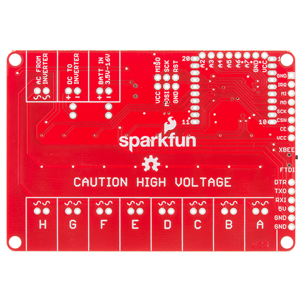
The VCC and GND screen printing on the front is reversed on the back. It's A2, A3, A4, A5, A6, A7, VCC, GND on the top but A2, A3, A4, A5, A6, A7, GND, VCC on the back.
the specs aren't clear about what's voltage is provided for the nrf24. Is it 5V? or 3V? (the breakout board supports both) I"d like to use that pin to provide power for a different device. Is there anything stopping me from using it in such a manner?
Unless of course, i missed another pin that provides when reading the sheet.
So if I want to use a 12v inverter I need two different power sources, right? Will the sequencer only work at 3 or 5 volts? Thanks
Nope, the Sequencer has an on-board regulator, so you can run both the sequencer and your inverter on 12V. Give the Sequencer 12V at the "batt in" connector. If you put a drop of solder on SJ1 to close it, the input 12V will also pass through to the "DC to inverter" connector for your inverter. Have fun!
Lot of thanks!
I have connected to EL wire, 12v EL Inverter to SparkFun EL Sequencer but it does not work (no battery is connected). The connections are the same like in Hookup Guide (https://cdn.sparkfun.com/assets/learn_tutorials/3/6/9/ELSequencerHookUp_bb.png). Furthermore, there is no light indicating that it works but I hear a noise/whistle from the Inverter.
Do I have to program the EL Sequencer or does it automatically turn the EL wire on?
You need to have a power source connected to your board in order to run the board, as well as the 12V power source connected to the inverter. If you want to run the system off one power source, then you should go with the 3V inverter and run the whole system off of the board battery.
The EL sequencer is preloaded with code to run the EL wire when you receive it.
Do y'all have any code for this product to use with chasing EL wire (https://www.sparkfun.com/products/12930)?
I looked around the Sparkfun account on Github, but did not see anything for chasing EL wire.
Here is a video of the project we made for our high school that uses this product. The EL sequencer is running the code linked below with the blue chasing EL wire (the plum on the knight's head).
https://www.youtube.com/watch?v=6h0d6na3S3o
You can actually use the standard code and play around with the timing of the strands turning on/off to see how the chasing wire will speed up or slow down.
Here is a link to the source code for chasing/flowing EL wire, using this sequencer: https://github.com/onebeartoe/electronics/tree/master/el-sequencer/chasing_el_wire
Yep. That was the plan, if there is no source code available that demonstrates how to use this with the pigtail (https://www.sparkfun.com/products/12934). Thanks, anyhow! I'll update if I figure out the sequence to make it look like the EL is chasing.
I'd really like to see a ten channel version. Any possibility of bringing one out?
We don't currently have one in the works, but the circuit/schematic could be modified easily enough to create one.
This is a really cool idea for a board. Any chance this could be shrunk down? It's a big board in a world where boards are getting really small.
Maybe a muti-connector or something smaller that go out to pig tails with JST to the EL Wire to reduce size? Update the 328P to at least a 32u4 to remove other componets. Wireless with 8266 (or replace the full controller with your THING board) or bluetoothLE. Oh, I just noticed it doesn't have a USB port as well. An FTDI cable is fine but a micro USB would be better.
Don't get me wrong, I like the idea of this board a lot. If the concept was thought of more in the realm of a wearable sized item it would have so many more uses. The board can only get so small, but with newer microcontoller, wireless, USB, and possibly combo output connector to the EL Wire it might be half the size.
All just idea's...
It's definitely worth looking at. However, a lot of the board size comes from the required TRIACs that actually drive the EL channels, and the required PCB space for proper functionality of those. You could certainly go smaller, but you'd likely have to cut out a few channels of EL wire.
Hey Toni, thanks for the reply.
I hear you on the TRIACs...I was guessing that was some of the size. I do howver think the connectors could be off boarded. I'm not sure the correct engineering to make that work but sometype of cable bundle. Maybe the power requirements cause havic with this idea as well?
What about ditching the controller side all together like your sheild, I think that's still for sale, but make the board as small as technically possible. Then use a stacking method with your thing board or other smaller sized boards. The arduino headers make things simple but projects get kind of big. I've been digging the new set of mini boards out (from SF and others) that stack.
This is a very cool idea and I've not seen many baords that handle EL Wire to sequence. But this would be so much cooler if it was wearable and wifi. If nothing else just update the microconroller and add micro usb. That would make it simpler to use as well. I could see this as a fun MakeyMakey-like board but for EL.
Again...excellent stuff and these are just ideas.
Schematic and Eagle files links are 404 Not Found!
Ah I see the problem. Too many EL entries.