SparkFun Block for Intel® Edison - I2C
The Intel® Edison is an ultra small computing platform that will change the way you look at embedded electronics. Each Edison is packed with a huge amount of tech goodies into a tiny package while still providing the same robust strength of your go-to single board computer. Powered by the Intel® Atom™ SoC dual-core CPU and including an integrated WiFi, Bluetooth LE, and a 70-pin connector to attach a veritable slew of shield-like "Blocks" which can be stacked on top of each other. It's no wonder how this little guy is lowering the barrier of entry on the world of electronics!
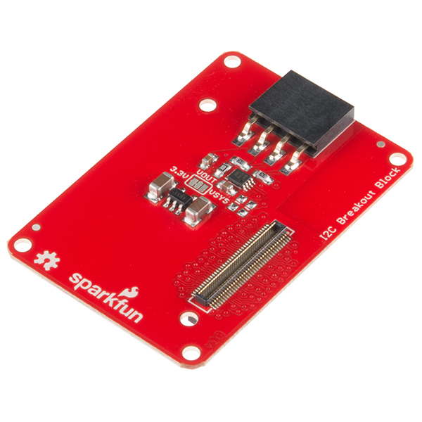
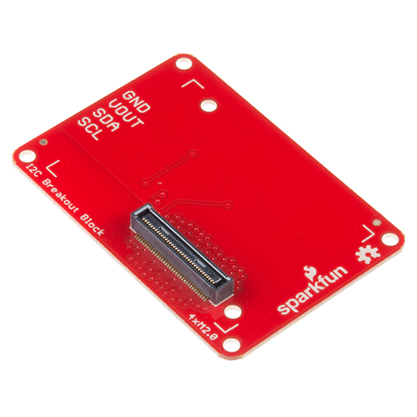
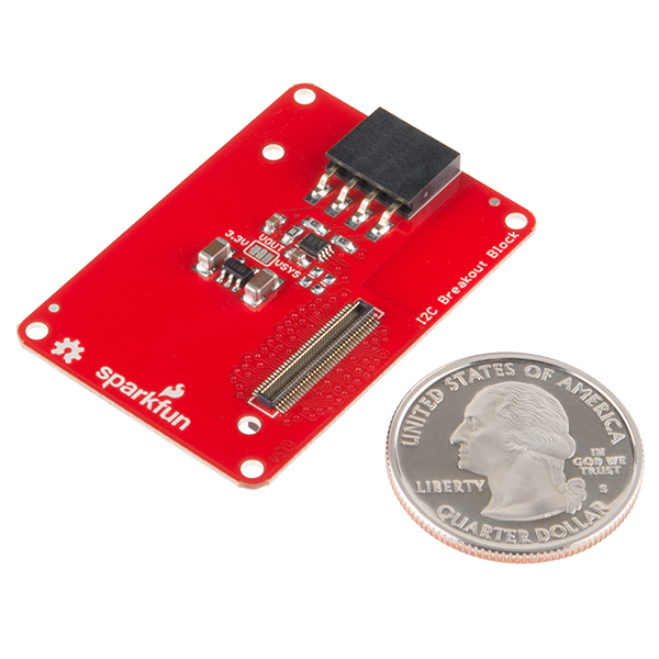
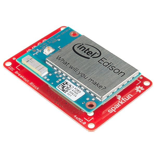
This I2C Block simply breaks out an I2C bus on the Intel® Edison while level shifting it from 1.8V to your sensors voltage. This a simple board that can snap into your Edison and be used right away.
If you are looking to add a little more stability to your Intel® Edison stack, check out this Hardware Pack. It will provide you with increased mechanical strength for stacking Blocks on your Edison!
SparkFun Block for Intel® Edison - I2C Product Help and Resources
Edison Getting Started Guide
December 5, 2014
An introduction to the Intel® Edison. Then a quick walk through on interacting with the console, connecting to WiFi, and doing...stuff.
SparkFun Blocks for Intel® Edison - I2C Breakout Block
January 15, 2015
A quick overview of the features of the I2C Breakout Block.
Programming the Intel® Edison: Beyond the Arduino IDE
January 7, 2015
Intel's Edison module goes beyond being just another Arduino clone. Check this tutorial for advice on how to get the most out of your Edison by writing code in C++!
General Guide to SparkFun Blocks for Intel® Edison
January 5, 2015
A general guide for using SparkFun Blocks for Intel® Edison in your next project!
Loading Debian (Ubilinux) on the Edison
December 5, 2014
How to load a Debian distribution (specifically Ubilinux) onto the Edison.
Installing libmraa on Ubilinux for Edison
January 5, 2015
libmraa is a tool kit for interacting with various Intel single board computers.
Core Skill: Programming
If a board needs code or communicates somehow, you're going to need to know how to program or interface with it. The programming skill is all about communication and code.
Skill Level: Competent - The toolchain for programming is a bit more complex and will examples may not be explicitly provided for you. You will be required to have a fundamental knowledge of programming and be required to provide your own code. You may need to modify existing libraries or code to work with your specific hardware. Sensor and hardware interfaces will be SPI or I2C.
See all skill levels
Core Skill: Electrical Prototyping
If it requires power, you need to know how much, what all the pins do, and how to hook it up. You may need to reference datasheets, schematics, and know the ins and outs of electronics.
Skill Level: Rookie - You may be required to know a bit more about the component, such as orientation, or how to hook it up, in addition to power requirements. You will need to understand polarized components.
See all skill levels
Comments
Looking for answers to technical questions?
We welcome your comments and suggestions below. However, if you are looking for solutions to technical questions please see our Technical Assistance page.
Customer Reviews
No reviews yet.


It is unclear to me if you can run this board at the 1.8V like the mini breakout. I have a 5V signal and use an external level shifter, so it seems more logical to just shift to 1.8 externally, and not to 3.3 for this block. So if jumper is not used, is it 1.8V ?
Does this I2C block allow the connection of the MCU I2C (I2C_6)?
Has anybody tried this with sparkfun TMP102 break out board? We have been trying and although the tmp102 board works perfectly with arduino uno, it is not detected by intel Edison. Double checked wiring etc... any help apreciated
Can I use a GPIO Block to setup an interface with I2C device (e.g. LiPo Fuel Gauge) instead of this block?
Anybody ever tried to use that block with a mics_vz_89t air quality sensor ( 3.3V I2C ) ?
If I set the voltage jumper to VSYS, would there be any problem with powering the whole stack by providing 4.5V at JP2?
Trying to use this block with a level shifter on the jst connector.
I can run: i2cdetect -y -r 1
And I get:
root@BIG_BOARD:~# i2cdetect -y -r 1 0 1 2 3 4 5 6 7 8 9 a b c d e f 00: -- -- -- -- -- -- -- -- -- -- -- -- -- 10: -- -- -- -- -- -- -- -- -- -- -- -- -- -- -- -- 20: -- -- -- -- -- -- -- 27 -- -- -- -- -- -- -- -- 30: -- -- -- -- -- -- -- -- -- -- -- -- -- -- -- -- 40: -- -- -- -- -- -- -- -- -- -- -- -- -- -- -- -- 50: -- -- -- -- -- -- -- -- -- -- -- -- -- -- -- -- 60: -- -- -- -- -- -- -- -- -- -- -- -- -- -- -- -- 70: -- -- -- -- -- -- -- -- root@BIG_BOARD:~#
So the Edison does see the LCD, it just isn't working otherwise.
I have hooked this up to an Edison sitting on the arduino breakout and it works just fine.
Not sure what the issue is here.
The Schematic has 200K resistor from VREF2 to VCC but the board has 300K.
Any reason for that?
I wanted I2C block to work with TMP-102 sensor. Won’t. Using i2cdetect replies with errors “i2c_dw_handle_tx_abort: lost arbitration.” Using pull up resistors from 680 to 10k changed nothing.
I am trying to add a UART to the edison over i2c using this block and the SC16IS750 breakout (https://www.sparkfun.com/products/9981) because the Edison has only one UART and I need to attach 2 or 3, but it is not detected. I've set the device address to 0x94 on the SC16IS750 which should be detected as 0x4A I believe. I tried 'i2cdetect -r 1' but it is not detected. When attached, I do detect the SparkFun Block for Intel Edison - ADC on address 0x48 for what it's worth.
Any hint on using this interface?
I am seeing about 6 holes near the hirose connector. Instead of stacking the edison to this block, can I bring-in 5 lines (VSYS, 1.8V out, SDA, SDC, GND) from the mini-breakout and then connect them to 5 of the 6 holes, would it work ? If so, which hole correspond to which line ?
If you are looking for an I2C level shifter may I suggest our PCA9306 Breakout? Those holes are 13mil vias. Not suitable for soldering.
ah, ok. Yes, since I am already breaking out the I2C pins from the mini-breakout, all I needed from this block was the level shifting. I will check out PCA9306. Thanks that helps
You can stack the I2C block on the mini breakout. you might need to trim the jumpers on the Mini Breakout to make clearance for the I2C header. That might save you a step and make a cleaner stack. Good luck!
Hi SF! There are no Blocks containing I2S (audio codec) signals. Most often they are used with I2C so please adding I2S signals to this board or creating a new one with I2S + I2C + SPI signals.
Alternatively or additionaly consider creating Audio Codec Block using CS42L51, CS42L52 or TLV320AIC3204 which are Low-Power versions and dosn't require level conversion for the signal. Also these codec is supported in ALSA ASoC drivers.
An audio Block is in the works. When? Not sure.
can i power edison with this?
No, you must use a Console Block, Base Block, Battery Block, or with caution a GPIO Block.
Wait....the video states bus lines can support 3.3v-4.5v devices. The description above says it can " level shifting it from 1.8V to your sensors voltage."
So which is it? And is 4.5v really the max? So if I were to hook up an Arduino as an I2C slave then that would not be a good thing.
The original design was the sensor supplied the reference voltage. We are rev'ing this to include a 3.3v LDO. We will have a jumper to select the 3.3v bus OR VSYS (3.3 - 4.5v). We were trying to support 5v devices but it looks like without a solid 5v boost it's not seeming feasible unless you were to supply it externally. There will be a way to use 5v with the board but it will be a "white wire" hack that will require an external 5v supply.
exactly how many I2C channels can be addressed by the Edison? how many, then, in theory could be stacked together?
If by channels, you mean devices? That's limited by the I2C Spec at 128 devices. This board may be stacked to provide multiple level shifted outputs. However these will be all on the same bus. The purpose of this board is to simply protect the I2C on the edison from higher voltages used by common sensors.
thanks does help a bit conceptually. My question comes from the scenario where I have 2 devices in serial on the same bus from a wii chuck and motion sensor, and I'm wondering if I'll need to split them or would I be able to address them both off the single board. Assuming that it's sketch compatible, I'm assuming it should as simple as re-factoring the code for the right interface? or is there a new way to handle I2C on these devices with yocto?
I don't mean to be that guy... but shouldn't "We do not currently have an estimate of when this product will be back in stock." Be "We do not currently have an estimate of when this product will be in stock."
As Pre-Order implies it's never been in stock?
Does the Edison require pull-up resistors on the I2C, or are those already on the board. If the Edison doesn't add the pull-up resistors, does this board have the resistors?
No need to add resistors- they're included!
Maybe it is just me but I hate it when pullups are added onto I2C devices. Some sensors have pullups on them and they just cause problems if everyone pulls up the damned I2C bus. I even turn off Arduino's pullups on the SDA/SCL line. Sorry for rant.
We typically include I2C pullup resistors on our products but add a solder jumper to allow disabling them if needed.
The announcement video mentioned that the I2C block level shifts up to input (system) voltage of the Edison (3.15 to 4.5 V). Have you considered adding a jumper on the board to allow the 'high' voltage to be tied to the 3.3v (@250mA) regulated output that is coming out of the Edison's PMIC?
There is talk of adding an external VReg to address this.
We've considered it. In the end, we decided to pull from Vsys and regulate down on individual boards when needed to avoid loading that 3.3V bus.