SparkFun RS232 Shifter Board Kit
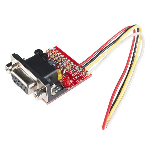
Get your PIC or other uC talking to your computer fast and easy with this board! This is a small custom PCB developed to connect the UART on a microcontroller directly to the computer without the hassle of a MAX232 circuit. Almost all current computers (less than 10 years old) utilize a serial port based on the EIA-232 standard which operates from +/-3-12V rather than the RS232 standard of +/-12V. This board takes signals from the computer/microcontroller and correctly inverts and amplifies the serial signals to the EIA-232 standard. Works great up to about 38400bps. Originally designed to get Bloader working in a bread-board setup, we use our Shifter at 115200bps without problems.
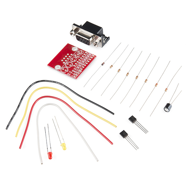
Comes as a bag of parts kit and is easily assembled if you can follow the silkscreen indicators and have beginning experience with a soldering iron.
Checkout our soldering tutorial to assemble this device.
- Qty 1 : DB9 Female Header
- Qty 1 : 2N3904
- Qty 1 : 2N3906
- Qty 1 : 1N4148
- Qty 5 : 10K Ohm
- Qty 2 : 220 Ohm
- Qty 2 : Basic LEDs
- Qty 1 : 10uF
- Qty 4 : 5" Wire
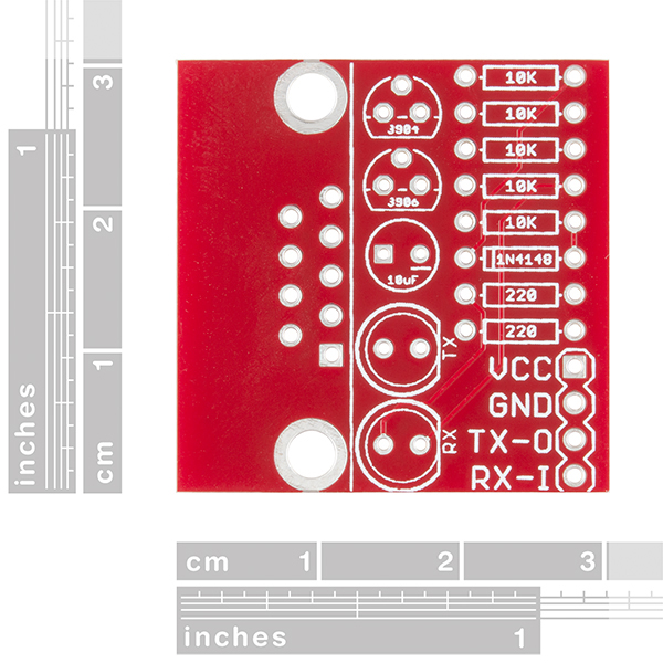
- 1.25x1.15"
SparkFun RS232 Shifter Board Kit Product Help and Resources
Core Skill: Soldering
This skill defines how difficult the soldering is on a particular product. It might be a couple simple solder joints, or require special reflow tools.
Skill Level: Rookie - The number of pins increases, and you will have to determine polarity of components and some of the components might be a bit trickier or close together. You might need solder wick or flux.
See all skill levels
Core Skill: Electrical Prototyping
If it requires power, you need to know how much, what all the pins do, and how to hook it up. You may need to reference datasheets, schematics, and know the ins and outs of electronics.
Skill Level: Rookie - You may be required to know a bit more about the component, such as orientation, or how to hook it up, in addition to power requirements. You will need to understand polarized components.
See all skill levels
Comments
Looking for answers to technical questions?
We welcome your comments and suggestions below. However, if you are looking for solutions to technical questions please see our Technical Assistance page.
Customer Reviews
3 out of 5
Based on 1 ratings:
Warning: this kit passes only TX/RX, no handshake lines!
Warning: this kit passes only TX/RX, no handshake lines! Board quality & parts seem OK, but I couldn't use it.
I failed to notice that it was TX/RX-only looking at the illustration. That's insufficient for my application, which requires me to be able to pass the 1PPS signal from a bare -wire GPS-18.
A version that can level-shift RTS/CTS/CD/RI would be a big improvement. Even just CD would be enough for a large class of applocations.
Hi, You are correct in that we only make use of the primary communication lines. So sorry that these did not work for your needs. Happy hacking. Thanks.

I'm kind of confused by the description. Does it work up to 115200 or 38400?
I second that. 115200 is needed (reliably) for my intended use. Not "maybe, sorta".
How about some clarification Sparkfun ?
I have connected it to Arduino Pro and can only receive from Arduino but would not transmit. Why? I'm going to send back this and ask about refund.
Will this work if supplied with 3.3V?
Does anyone know the purpose of the capacitor in this circuit and why it is reversed?
The capacitor is part of a charge pump. It is reversed because RS-232 logic high is represented by a negative voltage. More info can can be found here.
The design is pretty ingenious but shouldn't that work only in half-duplex? If the RS-232 device is sending a 0x00 byte (ie TX stays at a positive voltage), wouldn't the capacitor gets depleted if on the other end we're setting our TX (RX on the schematic) low hence the device's RX to +5V? Then the next "1" sent to the RS-232 would be 0V instead of -9V which seems rather problematic.
It's still of great help whenever there's no MAX232-like ICs around but the description is misleading if it's not equivalent
Will this work with the Wiznet Serial-to-Ethernet adapter for hooking up a microcontroller to the internet?
I currently use a windows slate for all my work but it doesn't have a serial port. Could I use a USB to serial adapter cable to use this with my computer's USB port?
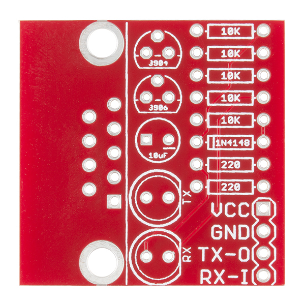
There are part-numbers on the schematic (e.g. Q1, Q2, R1, etc) but they're not on the PCB.
What the hell?
I want to bodge together a custom adapter that does TTL level-shifting (5v-3.3v), and I'm stuck following traces to figure out what is what.
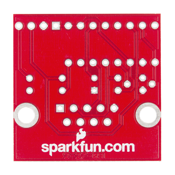
There is enough space on the board for part deliminators, and you have double-sided silkscreen (there is a logo on the bottom. and nothing else). Would it kill you to label stuff?
Need to have a version that fits inside the DE-9 shell. The board can fit between the 4 and 5 pin sodler cups on back of solder DE-9 connector (male or female).
An SMT MAX232 could then fit as well !!
I just spent several days trying to figure out a problem with a data communication project. It was traced back to this level converter. As mentioned/quoted by Paradoxial this type of "voltage stealing" converter may not work particularly well in all situations. Using a "real" level converter (using something like a Maxim 232 chip) might be a safer bet.
I love Sparkfun products, but this is one I can't fully recommend. It worked OK on an Arduino but not on other projects.
If I'm using this to connect a 5v Arduino Pro with a device that expects the full +/- 12V, should I set Vcc to 12V, or to 5V?
Note that if your serial signals are 3.3V, and you supply the board with 5V, your logic "1" will probably not be high enough to fire.
RussNelson:
Would this allow me to connect an openlog directly to a serial port to replace a serial printer?
Yes it works... I tested it! It works with 3.3V the same well as 5V!