SparkFun LED Array - 8x7
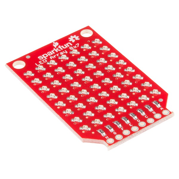
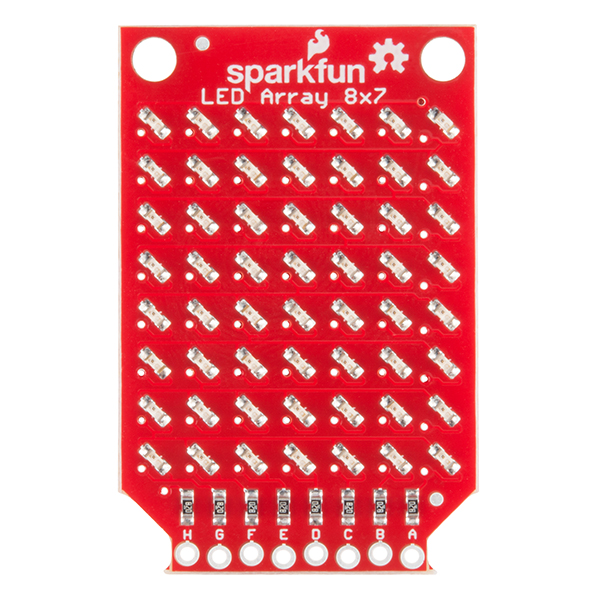
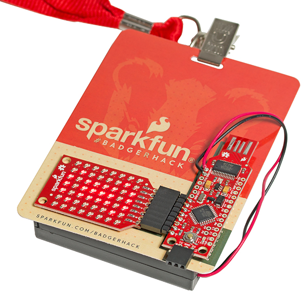
The SparkFun LED Array is a set of 56 red LEDs arranged in a nice 8x7 grid. This little board requires eight pins while the library supports any ATmega 168 and 328-based Arduino device. The SparkFun LED Array was developed to be used in conjunction with the BadgerStick as a fun and interactive way for people to learn about soldering and engage with SparkFun products at the multiple trade shows we appeared at. Now this LED array is available to everyone!
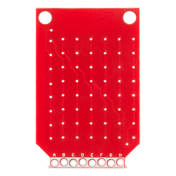
This board relies on the Charlieplexing technique to control individual LEDs, which means less GPIO pins are used (as opposed to a traditional grid format). Through the use of Charlieplexing we have been able to control all 56 LEDs with a total of only eight pins (labeled 'A' through 'H'). With a little bit of code you will be able to cycle through all combinations of the pins to turn each LED on individually, and if cycled fast enough, you can create simple images and text!
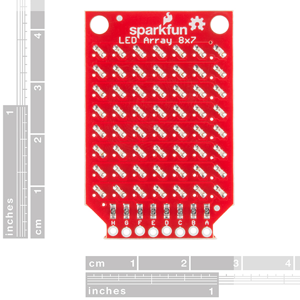
- 43.75mm Long x 28.5mm Wide
- Schematic
- Eagle Files
- Hookup Guide
- All About LEDs
- GitHub (Design Files & Example Code)
- GitHub (Library)
SparkFun LED Array - 8x7 Product Help and Resources
BadgerHack: Gaming Add-On Kit
February 16, 2016
Make a Breakout clone with the BadgerHack Gaming Add-On Kit.
SparkFun LED Array (8x7) Hookup Guide
March 10, 2016
Getting started with the Charlieplexed 8x7 LED array.
Core Skill: Soldering
This skill defines how difficult the soldering is on a particular product. It might be a couple simple solder joints, or require special reflow tools.
Skill Level: Noob - Some basic soldering is required, but it is limited to a just a few pins, basic through-hole soldering, and couple (if any) polarized components. A basic soldering iron is all you should need.
See all skill levels
Core Skill: Programming
If a board needs code or communicates somehow, you're going to need to know how to program or interface with it. The programming skill is all about communication and code.
Skill Level: Rookie - You will need a better fundamental understand of what code is, and how it works. You will be using beginner-level software and development tools like Arduino. You will be dealing directly with code, but numerous examples and libraries are available. Sensors or shields will communicate with serial or TTL.
See all skill levels
Core Skill: Electrical Prototyping
If it requires power, you need to know how much, what all the pins do, and how to hook it up. You may need to reference datasheets, schematics, and know the ins and outs of electronics.
Skill Level: Competent - You will be required to reference a datasheet or schematic to know how to use a component. Your knowledge of a datasheet will only require basic features like power requirements, pinouts, or communications type. Also, you may need a power supply that?s greater than 12V or more than 1A worth of current.
See all skill levels
Comments
Looking for answers to technical questions?
We welcome your comments and suggestions below. However, if you are looking for solutions to technical questions please see our Technical Assistance page.
Customer Reviews
4.7 out of 5
Based on 3 ratings:
Great display!
These are awesome displays, perfectly sized for fitting to glasses for that secret-agent look. It'd be nice if there were more tutorials on how to create images, slideshows, text, etc, but I expect those will come soon enough now that the display is for sale and not just a badgerhack giveaway. Reliable display, capable of some very cool stuff.
Easy to use and a lot of fun
This board is perfect for use with the Pro Mini boards because it lines right up with the I/O pins. It didn't take any time at all to have it up and running and making cool patterns like rolling sine waves.

8x7? cringe Wai u no 8x8?
Yes, I know it would take 9 pins to do 8x8, but I would sacrifice another pin for 8x8
I'd argue the 8-pin route is better.
9-pins spans more than one port on AVR controllers. If it was 9 pins, I'd have to :
It is double the code your way.
8-pins is much better and allows for more compact code.
Paired with the Redstick, though, it'd be awkward to get 8 I/O on a single port anyway. The only 8-bit I/O port that's fully available is port D (as two pins of port B are used for the oscillator). But two pins of port D are used for the UART, and (on the Redstick, at least) are physically separated from the rest of port D.
...But yeah, can you even imagine setting those I/O lines one at a time like Arduino encourages you to? :)
Arduino is great to get people into the hobby of embedded space, but in professional practice, it makes me cry
It's Charlie-plexed and uses 8 I/O lines. 8x7 is the maximum size under those conditions.
Basically, to light a LED you choose one I/O line to apply positive voltage to, and one to apply negative voltage to. When you select the line for positive voltage it can be any of the 8. But when you select the one for the negative voltage, it can't be the same one you chose for the positive voltage, so you only have 7 choices. Thus, 8x7.
I know exactly how charlieplexing works. I'm saying I'd rather use 9 pins to do 8x8 than 8 pins to do 8x7
Well the way you phrased the question sounded like you didn't. If your comment about using a ninth pin was in there when I replied, I guess I missed it. Sorry, didn't mean to explain something you already understood.
Don't know specifically what went into their design decisions there. I suppose they were trying to strike some balance between capability and economy, given that this was originally a give-away item.
No, it was definitely unclear when I posted it. I edited shortly after, and you probably read it in between the original post and the clarified post. No worries.
Overall, this looks like a great product. Making such a large array in a small package with just eight IOs is a fantastic idea. However, the lack of contrast between the red light of the LEDs and the bright red silkscreen appears to be a drawback.
To my eyes, when looking at both the pictures provided and the showcase video, it's difficult to discern the lit from the unlit LEDs. In the video, even when the ambient light is turned down somewhat, the array is still not quite distinctive enough. I can understand the reasons: red LEDs are typically cheaper, power consumption versus brightness is an issue and, being a Sparkfun product, it's natural to make the silkscreen red for both branding and cost. If it is going to be operated in at least near darkness or some kind of contrasting cover to shine through is used, then I suppose my concerns are probably irrelevant. Otherwise, I think changing the colour of either the silkscreen or the LEDs should be considered to make it a more useful product.
Thanks for the feedback! We'll definitely consider multiple colors for possible revisions.
Are there any plans to make this with rgb or white LEDs?
Not at this time. RGB in this form factor would be hard, as you would need 24 pins to keep Charlieplexing. If there is enough interest for other colors, we might make them :)
SparkFun . . . you can go DENSER:
http://i.imgur.com/J53FeSN.jpg
That's an 8x8 array of 0603 LEDs with an outer dimension of 2/3 inch
Also, on a side note, I had to reset my password for my account to comment (which required me to respond to an e-mail link) and then I had to verify my e-mail . . . which was funny.
I played with a denser layout, but ultimately decided to space them out more to make the 8x7 look bigger, which worked well as an event giveaway.
Product Suggestion: Redo layout so input pins (a-h) are on top or bottom with additional space for mounting holes and eliminate the extra board space where existing mounting holes and logo are now.. Reason: Would allow for left to right stacking of these to create a scrolling LED display 8Xn number of boards. Would need GPIO expander(s) and LED driver(s) but would offer next step in experimentation.
+1 for fixing the spacing so you can tile the boards left to right. You're sooo close....
Yes finally you guys offer charlieplexed led boards! This should have been done a long time ago but I'm so glad its finally here
What are the dimensions of the board? And what color are the LEDs? (It looks like just red from the tutorial?) Are they RGB?
If you check the second image on the product we've put rulers up.
The board is 4.375 cm long and 2.85 cm wide.
Also, the LEDs are red. :)
they are not RGB. you could theoretically do RGB with charliplexing, but it would require using almost all the IOs of an Uno.
I would expect red since that's what the schematic and tutorial say, but I guess that could change in the future.
The GitHub link Design Files & Example Code is not correct (404)
Sorry about that! I just made the repo live, so it should work now.