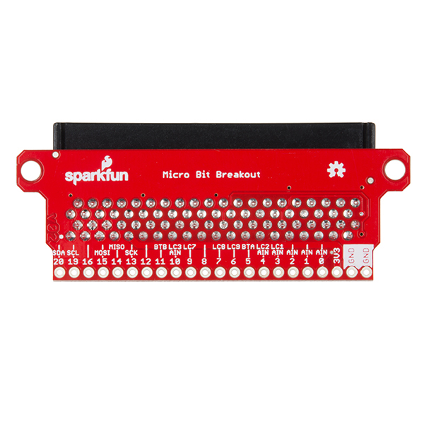
SparkFun micro:bit Breakout
The SparkFun micro:bit Breakout is a board that connects to the BBC micro:bit and expands the capabilities of the development platform by providing access to more pins and allowing for connections to the I2C and SPI buses. This breakout board for the micro:bit’s edge connector allows intermediate and advanced users to connect the micro:bit to breadboards and other sensors, motors, LEDs and more!
The micro:bit on its own has three digital/analog input/output rings available for you to use initially with alligator clips. With the micro:bit breakout we have broken out all 21 GPIO, power and ground-to-pin outs in a 0.1" formation. With this breakout you will be able to unlock the full potential of your micro:bit!
Note: No micro:bit or headers are included with this breakout; they will need to be purchased separately. If you would like a micro:bit breakout with headers already soldered on, be sure to check out this board's sibling.
SparkFun micro:bit Breakout Product Help and Resources
SparkFun Inventor's Kit for micro:bit Experiment Guide
July 21, 2017
This guide contains all the information you will need to explore the twelve circuits of the SparkFun Inventors Kit for micro:bit.
micro:bit Breakout Board Hookup Guide
June 17, 2021
How to get started with the micro:bit breakout board.
Wireless Remote Weather Station with micro:bit
May 11, 2020
Monitor the weather without being exposed to it through wireless communication between two micro:bits using the radio blocks! This is useful if your weather station is installed in a location that is difficult to retrieve data from the OpenLog. We will also explore a few different ways to send and receive data.
Core Skill: Soldering
This skill defines how difficult the soldering is on a particular product. It might be a couple simple solder joints, or require special reflow tools.
Skill Level: Noob - Some basic soldering is required, but it is limited to a just a few pins, basic through-hole soldering, and couple (if any) polarized components. A basic soldering iron is all you should need.
See all skill levels
Comments
Looking for answers to technical questions?
We welcome your comments and suggestions below. However, if you are looking for solutions to technical questions please see our Technical Assistance page.
Customer Reviews
4.7 out of 5
Based on 3 ratings:
Essential connector for micro bit.
Very well built i/o board/ connector for micro bit. Allows you to use one micro bit for several different projects.
Works great, needs docs
This worked perfectly for embedding the micro:bit into a Halloween costume last week. The one suggestion I'd give to Sparkfun is to document it. Tell me which way to insert the micro:bit. I had to follow the traces on the PCB to know that the LED array had to face "up". (All it would take is a single photo in the product page.) Also tell me what the pins are. It's not clear that "AIN 0" matches the large pin 0, which is called "P1" in the IDE. Give me a full mapping between the pin labels on this and the ones on the pins page of the micro:bit.
If you're going to do a second revision of this, it might help to put a 3.3 V regulator on it so that it can driven by a variety of batteries. As it stands only the USB jack has a regulator.
Great for creating small footprint projects
This breakout is great for when I need to create a small footprint semi-permanent project. I use it to solder the few lines I need in the project.


