Qwiic Cable - Breadboard Jumper (4-pin)
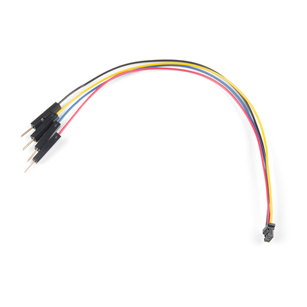
This is a jumper adapter cable that comes pre-terminated with a female Qwiic JST connector on one end and a breadboard hookup pigtail on the other. This cable makes it easy to connect components with a Qwiic connector to a breadboard or an Arduino-based device’s pins.
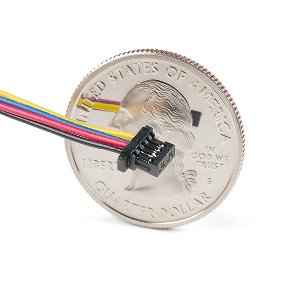
The 28AWG wire's length is 150mm (about 5.9 inches). The adapter’s wires have been color coded to red, black, blue and yellow. Additionally, the female Qwiic connector features a basic 1mm pitch, while the male hookup pins can easily insert into a standard 0.1" connector.
All Qwiic cables have the following color scheme and arrangement:
- Black = GND
- Red = 3.3V
- Blue = SDA
- Yellow = SCL
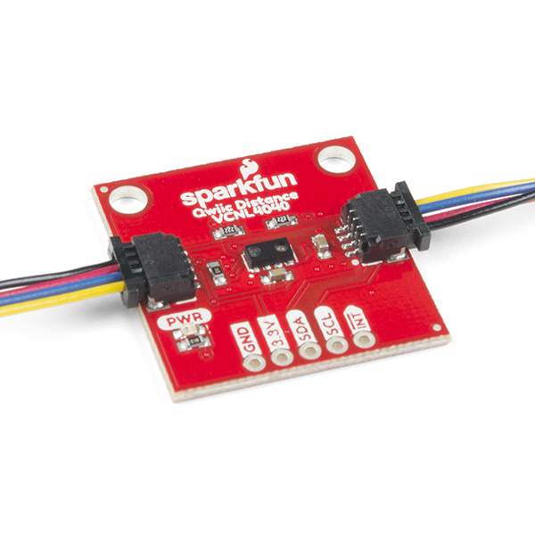
The SparkFun Qwiic connect system is an ecosystem of I2C sensors, actuators, shields and cables that make prototyping faster and less prone to error. All Qwiic-enabled boards use a common 1mm pitch, 4-pin JST connector. This reduces the amount of required PCB space, and polarized connections mean you can’t hook it up wrong.
- Dimensions: 150mm (5.9") Length
Qwiic Cable - Breadboard Jumper (4-pin) Product Help and Resources
Qwiic Transparent OLED HUD Hookup Guide
February 21, 2019
Learn how to connect that sweet transparent OLED.
Temperature Sensor Comparison
March 18, 2020
A comparison of analog and digital temperature sensors. Which is better?
Comments
Looking for answers to technical questions?
We welcome your comments and suggestions below. However, if you are looking for solutions to technical questions please see our Technical Assistance page.
Customer Reviews
No reviews yet.


Having an option for the female connectors at the breadboard end would be nice.
Thanks, Joe
Good idea! The Female Jumper is over here.
Nice! But I'd like to find both the connectors at the breadboard end, and the tools used to affix them.
Hello, I just received a "Qwiic Cable - Breadboard Jumper (4-pin)" to make a connection between the "SparkFun Spectral Sensor Breakout - AS7263 NIR (Qwiic)" and Arduino, but would like some important information regarding the meaning of the colors of the jumper. When connecting the qwiic to the sensor, the meanings of the jumper colors are Red: 3.3 Black: Gnd Blue: SDA Yellow: SCL?
Yep, you got the colors correct. :-) If you need a reference for the future, check our Qwiic landing page for the color codes.
Ideally to properly use this one, we'd need to know what the colors mean. But from other comments I was able to use the cable with the Pi Cap and a small breadboard. Now it is connected to a small OLED display which is supplying useful stats.
My next step will be to use the small cable with sockets on it to enable jumper wires to plug it into the same breadboard and different OLED displays.
I'm assuming red and black are vcc and ground. What are the other two colors (blue is SDA and yellow SLC or opposite)?
Just figured this out: Red: +3.3 Black: Gnd Blue: SDA Yellow: SCL