Bluetooth Mate 4.0 - HM-13
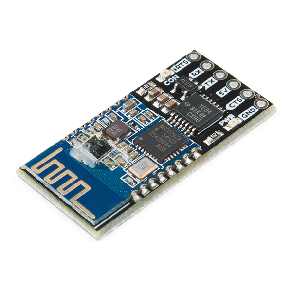
The Bluetooth Mate 4.0 is the next evolution in our line of serial Bluetooth modules. This board is equipped with an HM-13 module, which supports both SPP (Serial Port Profile) and BLE (Bluetooth low-energy) Bluetooth profiles via Bluetooth 4.0.
This board's HM-13 Bluetooth module supports both SPP (Serial Port Profile) and BLE (Bluetooth low-energy) Bluetooth profiles via Bluetooth 4.0. The HM-13's support for BLE means it's compatible with any smartphone. Or you can connect it to a computer via the old standard -- SPP -- and use it as a transparent Bluetooth data gateway. You can even use it in dual-mode, connected to a pair of devices simultaneously!
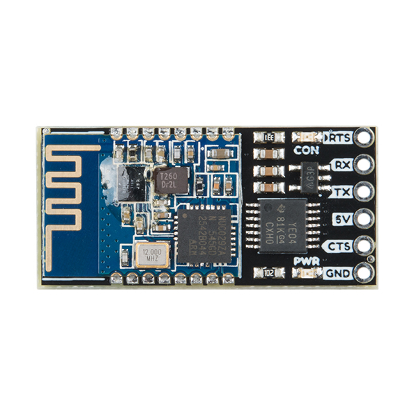
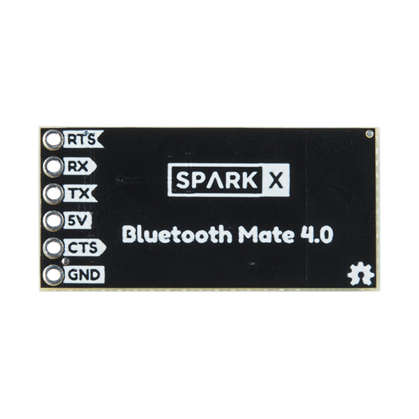
This board includes all of the voltage regulating and level shifting you need to interface either 5V or 3.3V microcontrollers with the Bluetooth module. Communication with the HM-13 is performed through a serial UART, and an AT-command structure is used to configure it.
In addition to the power-indicator LED, there is a green "CON" LED. When the module is disconnected, this LED will blink at 1Hz; when it's connected, the LED will be solidly on.
Check out our HM-13 Arduino library for help developing a Bluetooth app of your own! There are a handful of SoftwareSerial and HardwareSerial examples, which demonstrate how to set up a simple serial passthrough, how to adjust some of the module settings, and even set it up as an iBeacon.
Note: although the baud rate of these modules defaults to 115200, we set it to 9600 in production to make it a little easier to use with a SoftwareSerial port.
Experimental Product: SparkX products are rapidly produced to bring you the most cutting edge technology as it becomes available. These products are tested but come with no guarantees. Live technical support is not available for SparkX products. Head on over to our forum for support or to ask a question.
- Voltage level-shifting supports both 5V and 3.3V systems
- Designed to interface directly to Arduino Pro's
- Simple UART interface
- 4800-230400 baud
- Expansive AT command set
- BLE and SPP Bluetooth profile support
- Simulatenous and A-to-B mode support
- Built-in antenna
- Low power consumption: 13.5mA SPP, 9.5mA BLE
- v321 firmware
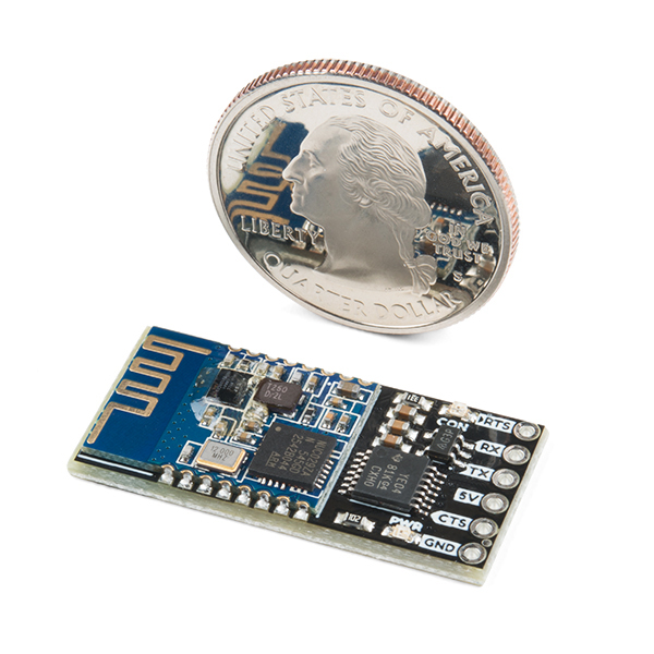
- 1.25 x 0.6"
Comments
Looking for answers to technical questions?
We welcome your comments and suggestions below. However, if you are looking for solutions to technical questions please see our Technical Assistance page.
Customer Reviews
No reviews yet.


I was having a lot of trouble getting this to work at first. I could send text through it from phone to PC (connected by UART) but not receive anything back; not from the PC or the AT command responses.
Eventually I realized this was just because the bluetooth terminal app I was using buffers until it receives a line break, but the module doesn't send them after AT commands. So I can issue an AT command from the phone, but have to then send the \r\n from the PC so that the app will actually show the AT response it received.
What's curious though is that the datasheet seems to imply that AT commands are only accepted from UART, not from wireless, but in my case, it seems to be the other way around; no response to AT commands over UART, only from my phone. Also, sending just "AT" doesn't terminate the connection, but returns OK as if not connected. I wonder if these modules somehow have mixed up which end is which?
Hi there, it sounds like you are looking for technical assistance. Please use the link in the banner above, to get started with posting a topic in our forums. Please, keep in mind that this is a SparkX and support for this product is handled a little differently.
Thanks, but I wasn't really looking for help, just remarking that it doesn't quite function how I expected.
I've also found that it consumes ~20mA, rather than the 9mA the datasheet describes...
Ahh... well, in that case, thanks for providing the pointers for other users.
As to the current consumption, could it be possible that you are measuring it for the whole board and not just the Bluetooth module? (*i.e. The logic level shifter and volage regulator seem to consume a negligible amount of current, but the additional current consumption could be from the 2 status LEDs.)
I was measuring the entire board. Can the LEDs really account for 11mA on their own?
The forward current on the LEDs is 20-30 mA (each). So yes, depending on how fast they are blinking and the voltage they are being driven at... they could potentially account for a majority of the current consumption you measured.
This discussion is getting into the technical assistance realm; please, post a topic in our forum for further assistance. Thank you.