SparkFun GNSS Chip Antenna Evaluation Board
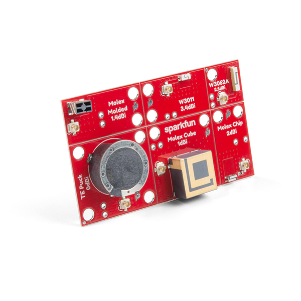
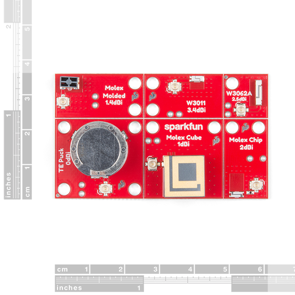
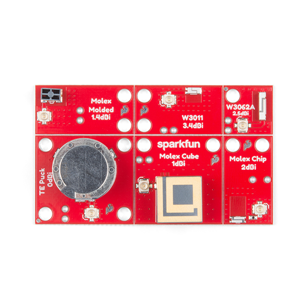
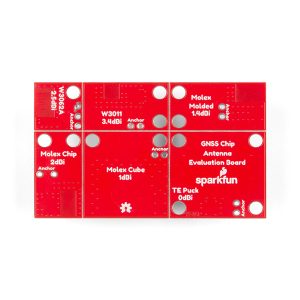
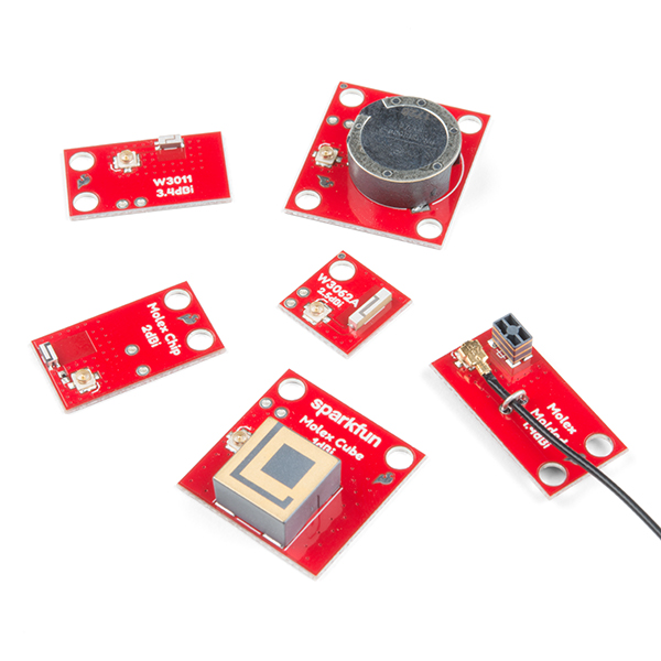
What is the best chip antenna for your GNSS project? There are tons to choose from, but finding the right one might be tricky so here's a board that helps make deciding easier. The SparkFun GNSS Chip Antenna Evaluation Board makes it easy to test out various sized GPS antennas and geometries. Six different chip antennas have been populated on this board, each with a U.FL connector to attach your chip to the antenna! We've even v-scored the board so you can snap the six antenna's apart and just have the one you need.
If you aren't picky about your antenna and/or each of the antennas work well for your applications, you will get six antennas to use in various project. Since these are GNSS antennas, they will work with GPS as well as GLONASS, Galileo, BeiDou, and other worldwide systems.
- Included on the Board:
- Chip Antenna Board - TE 1565-1585MHz Puck Single Band Antenna - 1513634-1
- Chip Antenna Board - PulseLarsen 1.575GHz GPS Ceramic Chip Antenna - W3062A
- Chip Antenna Board - PulseLarsen 1.575GHz GPS Ceramic Chip Antenna - W3011
- Chip Antenna Board - Molex Helix GPS Antenna - 146235
- Chip Antenna Board - Molex RHCP LDS-MID GPS Antenna - 146216
- Chip Antenna Board - Molex Low-profise GNSS Ceramic Antenna - 240283
- Schematic
- Eagle Files
- Hookup Guide
- Datasheets
- Dimensional Diagram - TE 1513634-1
- Datasheet - TE 1513634-1
- PulseLarsen Antenna Guide
- Datasheet - PulseLarsen W3062A
- Datasheet - PulseLarsen W3011
- Molex Antenna Guide
- Datasheet - Molex 146235
- Datasheet - Molex 146216
- Datasheet - Molex 240283
- GitHub Hardware Repo
SparkFun GNSS Chip Antenna Evaluation Board Product Help and Resources
Three Quick Tips About Using U.FL
December 28, 2018
Quick tips regarding how to connect, protect, and disconnect U.FL connectors.
SparkFun GPS Breakout (ZOE-M8Q and SAM-M8Q) Hookup Guide
April 4, 2019
The SparkFun ZOE-M8Q and SAM-M8Q are two similarly powerful GPS units but with different project applications. We'll compare both chips before getting each up and running.
GNSS Chip Antenna Hookup Guide
April 4, 2019
You've always wanted to experiment with those tiny GPS antennas. Now you can!
Core Skill: Electrical Prototyping
If it requires power, you need to know how much, what all the pins do, and how to hook it up. You may need to reference datasheets, schematics, and know the ins and outs of electronics.
Skill Level: Noob - You don't need to reference a datasheet, but you will need to know basic power requirements.
See all skill levels
Comments
Looking for answers to technical questions?
We welcome your comments and suggestions below. However, if you are looking for solutions to technical questions please see our Technical Assistance page.
Customer Reviews
5 out of 5
Based on 1 ratings:
Great board out of the blue
I didn't want to hunt around for a smt antenna replacement for the particle electron asset tracker. Then this came out and I ordered it immediately. The scores make it easy to break apart. It was surprising to see the best performance from the W3011 but hey i'll take it.

Hello, something is really wierd for me with this module. 4 out of 6 antennas present a short circuit in the Ohmic sense. This is not strange itself since this is the case for DC current only. But! The antennas are tested in your "GNSS Chip Antenna Hookup Guide" tutorial with the ZOE-M8Q board. And in ZOE-M8Q there is permanently 3.3V on the antenna connector (designed to supply active antennas). It goes through a coil and a small resistance on the module. So how it is possible that you tested the antennas with ZOE-M8Q, having permanently 3.3V on antennas being effectively a short circuit for DC currents? When I performed the tests (not being aware of the problem), my ZOE-M8Q board got very hot. Now I know, this was fortunately not the chip but the coil and the resistor acting as a heater. Indeed, the current was almost 300 mA what is generally consistent with the resistor value.
Do NOT make any decisions based on this board. Apparently the people who created this have never heard of matching networks. The only 2 antennas that are even close to being matched correctly are the 3011 (center frequency of 1.556 GHz) and TE Puck (1.612 GHz). The other antennas are so poorly matched (center frequency of > 2GHz) that you're really measuring the transmission line, not the antenna itself. That doesn't make them bad antennas; they've been placed on boards without the necessary caps and inductors needed to make them work well.
SparkFun – I have VNA and I can tell you the matching networks needed to fix this board. Please contact me if you're interested in fixing this!
Hi there, Please feel free to file an issue in the GitHub repository, with your suggestions. Otherwise, you can also modify our Eagle files directly and submit a pull request. I would be happy pass along your feedback/suggestions for improving the performance of this product to our team.
This is a great product that shows some creative thinking. Good job!
This comment made my day. Thanks!