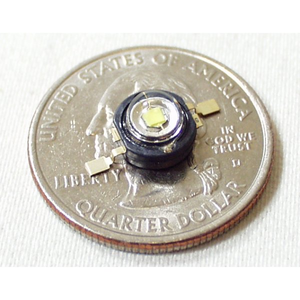
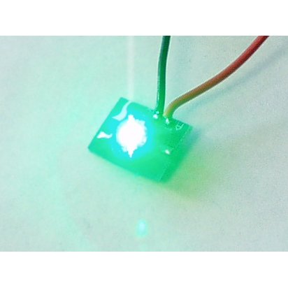
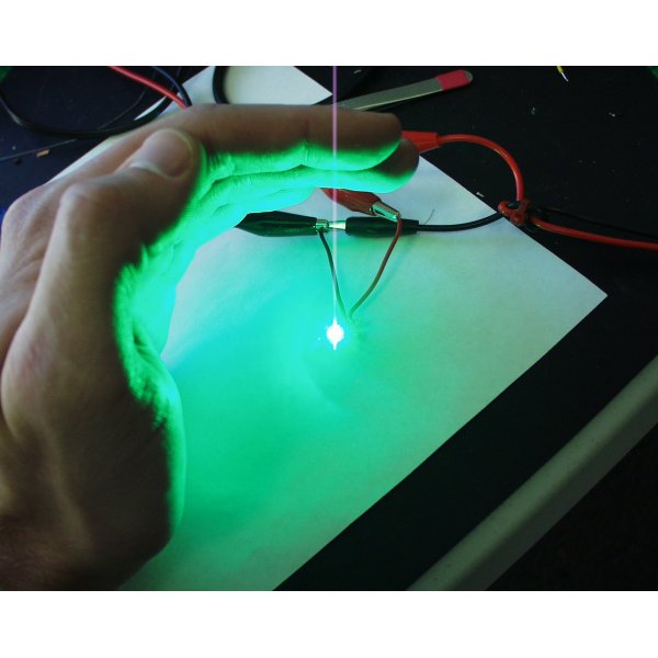
Luxeon I LED - White 1 Watt
Comments
Looking for answers to technical questions?
We welcome your comments and suggestions below. However, if you are looking for solutions to technical questions please see our Technical Assistance page.
Customer Reviews
No reviews yet.


For those of you trying to figure out how to wire this thing, you can see that on one side there is a second smaller leg with a small hole in it. This is the anode (+) lead. The other side with a single leg and no tiny hole is the cathode (-) lead.
I used an adjustable regulator to make a 3 brightness toggle for a light I made out of three of these LEDs. If you do it my way you just need to change the resistance across two of the pins on the regulator (check datasheet for specifics).
I used one of Dan's (at instructables.com) circuits as a starting point. He also outlined a circuit that is exactly what you're looking for:
http://www.instructables.com/id/Circuits-for-using-High-Power-LED_s/step8/a-little-micro-makes-all-the-difference/
Good luck
I am looking for someone sharp enough to figure out how to lower the input voltage on these leds. They appear to be fully dimmable. But for the life of me I can't figure out what I would need to do it.
A hand full of these make a great work bench light source. I want to use a microprocessor (aTiny or similar) to create a touch sensitive light switch that is able to turn several of these on to a desired brightness. Normally I'd use PWM to get the correct brightness, but these are way to powerful to run straight from a microprocessor. I am thinking somehow using one of these?
http://www.sparkfun.com/commerce/product_info.php?products_id=527
Ack!
If you are using a uP, don't lower the voltage to dim an LED. Instead, drive it with a PWM pin using a simple transistor amp. Look at the last circuit on this page:
http://www.techshire.com/freebies/LED4dummies.html
Likely parts are:
- A 2N2222 NPN transistor. It can handle up to about 1A of current to drive the LED.
-R2 on the transistor base should be around 1 kOhm.
- R1's value will be based on your supply voltage, the voltage drop of the diode, and the rate diode current. Use the formula:
R1 = [ V(supply) - V(diode) ] / Current(LED)
So if you are driving one of these LEDs at rated 350 mA from a 5V source, the R1 value would be
R1 = [ 5V - 3.42V ] / 0.350A = 4.5 Ohms.
The 3.42V value is the typical forward voltage drop for the diode from the datasheet. Be sure to pick an R1 that is capable of handling the power:
P(R1) = V(R1) * I(LED) = [ 5V - 3.42V ] * 0.350A = 0.55W
So pick a 1 Watt resistor to be safe.
Obviously, use your actual supply voltage in place of 5V in the above equations. And for the diode to work, the actual supply voltage must be greater than about 4V (since the max possible forward voltage drop for these LEDs according to the datasheet is 3.99V.)
Peter.
Thanks
3.4V
what is the maximum voltage you can apply to this LED?