LED Light Bar - Tri-Color
Replacement: None. We do not have a direct replacement for these. This page is for reference only.
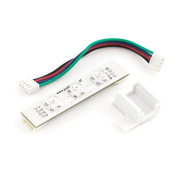
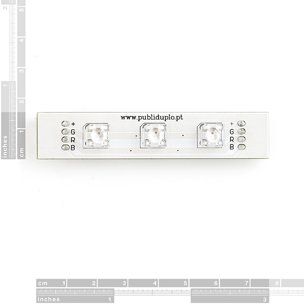
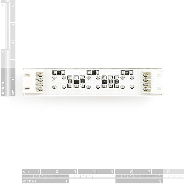
The LED Light Bar is a pre-packaged strip of 3 high-output Tri-Color LEDs powered by 12VDC. We don't have specifics on the output luminosity, but take a look at the example GPS Wall Clock project to get an idea. Each unit comes with a fully assembled and tested PCB with current limiting resistors, a wall-mount holder (backed with double-stick tape), and a connection cable. Each LED Light Bar absorbs approx. 90mA @ 12V with all three LEDs lit with all RGB lines active. The LED Bar is common Anode.
3.08x 0.59" (78x15mm) - Mounting hole OD is 0.176" (4.5mm)
More information about the 12' GPS Wall Clock can be found here.
Comments
Looking for answers to technical questions?
We welcome your comments and suggestions below. However, if you are looking for solutions to technical questions please see our Technical Assistance page.
Customer Reviews
No reviews yet.


"We don't have specifics on the output luminocity..."
Luminocity?
Luminocity is a window manager for X.
I put a 150 Ohm resistor in parallel with the red LED resistors to increase the brightness. It helps some, but will probably reduce the life of the LED's.
The green and blue channels are at least an order of magnitude brighter than the red. In order to do any sort of reasonable color mixing that includes red, I have to cut back the power on the blue and green significantly.
Very frustrating. Very disappointing.
The red LED on these is very dim compared to green and blue which will make it difficult to mix to white without seriously reducing the green and blue output. Might be able to change the resistor values, but that risks blowing them.
how would i add pwm to control these from the arduino if they are 12V?
Hmm, link to 12' GPS Wall Clock doesn't appear to be working at the moment...
Thanks for the heads up! We just changed some stuff around on the site - the link should be working now.
I took a stab at the current requirements for each R, G, & B at being about 2.2v 20ma for Red, and 3.5v 30ma for B & G. Because I needed to use a 5v source, I just re-flowed the resistors off, and replaced 'em with some 100ohm for the Red, and 150ohm for the Blue & Green. This helps considerably (but doesn't cure) the Red imbalance.
A little confused at how you got your values for green and blue unless you made them dimmer by having a larger value resistor to help with the low intensity of the red. 3.5 volts @ 30 ma with 5 volt supply should be in the range of 56 ohms right? I just got some of these and I think I will do the same as you cause I want to use them with the blinkm master.
I'm assuming that's 3 tri-color LEDs and not 1 each of red, green, and blue LEDs?