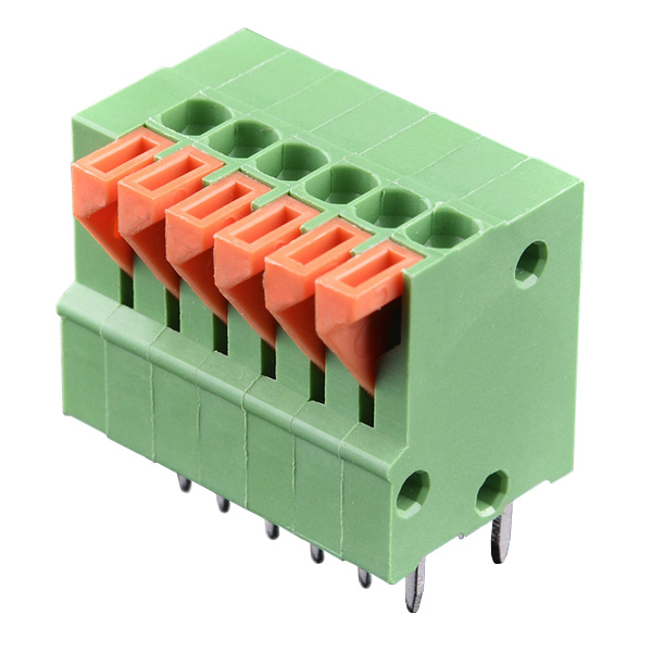
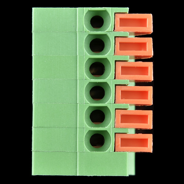
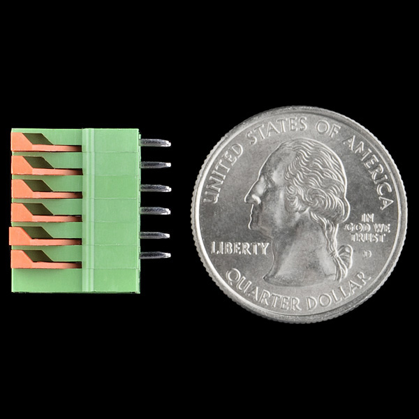
Spring Terminals - PCB Mount (6-Pin)
These are small spring terminals. Open the aperature with the small arm, insert the wire, release the arm and the wire is held firmly in place. This is a good quick way to to interface to bare wires. Capable of higher current and more resilient than breadboard or female header type connections.
Terminals with 0.1" standard spacing. Inserts directly into perf and proto board. Comes in 2, 3, 4, 5, and 6 positions. Rated up to 150V @ 2A. Terminal can accept 26 to 20AWG wire.
Spring Terminals - PCB Mount (6-Pin) Product Help and Resources
Connector Basics
January 18, 2013
Connectors are a major source of confusion for people just beginning electronics. The number of different options, terms, and names of connectors can make selecting one, or finding the one you need, daunting. This article will help you get a jump on the world of connectors.
Core Skill: Soldering
This skill defines how difficult the soldering is on a particular product. It might be a couple simple solder joints, or require special reflow tools.
Skill Level: Noob - Some basic soldering is required, but it is limited to a just a few pins, basic through-hole soldering, and couple (if any) polarized components. A basic soldering iron is all you should need.
See all skill levels
Comments
Looking for answers to technical questions?
We welcome your comments and suggestions below. However, if you are looking for solutions to technical questions please see our Technical Assistance page.
Customer Reviews
No reviews yet.


has anyone an Eagle component for these adorable connectors?
Yea, I was also able to pry off the end cap and string several blocks together to make a 24 pin and 30 pin terminal block. Just be careful. I snapped some of the pins that hold the end cap off by prying to hard. Here is a pic of the final parts soldered on my board.
Great pic of the super-long-spring-terminal-block! I will try this next time I need a longer bl
Ok I just got some and wanted to add a few comments.
Yes you can very carefully pry them apart just work around the circumference and go slow.
One big point, the male jumper wires I have are not long enough to engage the contacts. You need 3/8ths to one half inch of wire to work. the ones sold here appear to be even shorter.
why is there two pins for each pin? like for say the first pin has 2 pins below it as a connector to like a bread bord?
this is probably for mechanical support. With only one row of pins, The connector would rock slightly each time that the release arm was pressed. Over many cycles, the thin metal pins would fatigue and break. That is my guess anyway.
These do NOT match datasheet! The 3-wire version does, but these (6-wire) do not, they load from above and the geometry of the pins relative to the entire outline is shifted.
These are really useful.
I was able to gently pry the layers apart using an xacto blade. This comes in handy if you need less/more connectors. (I needed a cluster of eight)
Cool product at a great price. There is a discrepancy between the description and the datasheet regarding ratings, though. My application will encouter surges in excess of 2A, so I will err on the side of caution. If there is documentation to support the 6A rating, then this is my connector of choice!