PodBreakout
Replacement: None. The PodBreakout has been discontinued by the manufacturer so we can no longer carry it in our catalog. This page is for reference only.
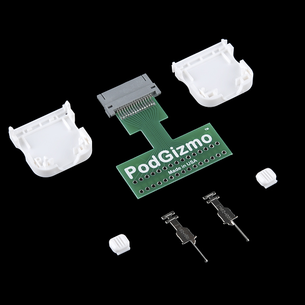
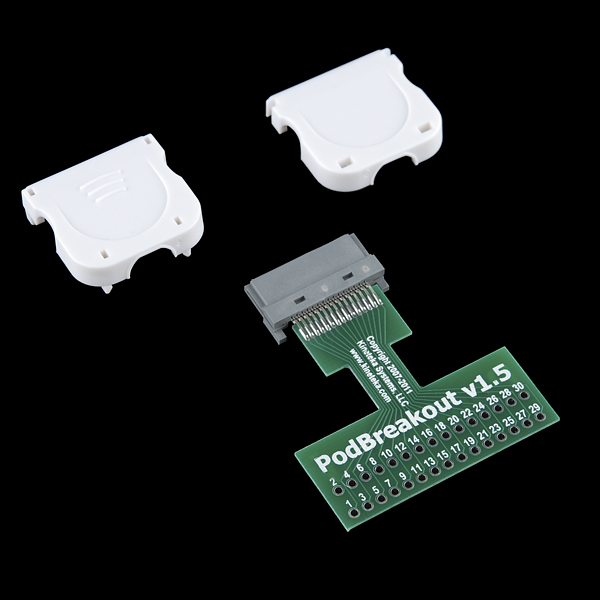
Don't think you can solder the tight pitch of the iPod connector? This is the breakout board for you. From PodGizmo comes the PodBreakout featuring the style 1 connector and a PCB with two rows of 0.1" spaced holes for easy cable and device creation.
PodBreakout Product Help and Resources
Core Skill: Soldering
This skill defines how difficult the soldering is on a particular product. It might be a couple simple solder joints, or require special reflow tools.
Skill Level: Noob - Some basic soldering is required, but it is limited to a just a few pins, basic through-hole soldering, and couple (if any) polarized components. A basic soldering iron is all you should need.
See all skill levels
Core Skill: DIY
Whether it's for assembling a kit, hacking an enclosure, or creating your own parts; the DIY skill is all about knowing how to use tools and the techniques associated with them.
Skill Level: Noob - Basic assembly is required. You may need to provide your own basic tools like a screwdriver, hammer or scissors. Power tools or custom parts are not required. Instructions will be included and easy to follow. Sewing may be required, but only with included patterns.
See all skill levels
Comments
Looking for answers to technical questions?
We welcome your comments and suggestions below. However, if you are looking for solutions to technical questions please see our Technical Assistance page.
Customer Reviews
No reviews yet.


Be aware that the v1.4 of this board has the wrong silk screen. I contacted Mike at Kineteka after people trying my iPodSerial project couldn't get it to work (I have v1.2 versions of this board). He said:
"There is a slight difference in the v1.4 due to a manufacturing glitch.
The boards still work the pinout is just flipped.
The pins are odd /even as opposed to even / odd.. see below.
Back side of dock connector v1.2
02 04 06 08 10 12 14 16 18 20 22 24 26 28 30
01 03 05 07 09 11 13 15 17 19 21 23 25 27 29
Back side of dock connector v1.4
01 03 05 07 09 11 13 15 17 19 21 23 25 27 29
02 04 06 08 10 12 14 16 18 20 22 24 26 28 30
So for instance the audio pins 3,4,5,6
PodBreakout Pin V1.2 V1.4
Right Line Out 3 4
Left Line Out 4 3
Right Line In 5 6
Left Line In 6 5
We are working on updating thehttp://www.kineteka.com/PodBreakout-v1.aspx page to reflect these
changes should be up soon."
WARNING: Pinouts seem to be reversed! See a href="http://ipodlinux.org/Dock_Connector" class="store-txt-grey" target="new"_http://ipodlinux.org/Dock_Connector/a_ for more information. Looks like I will have to re-label mine...
Just got an email from Kineteka that they'd updated their site with the 1.4 pinout:
http://www.kineteka.com/PodBreakout-v1.aspx
SparkFun: you should probably link to this page rather than pinouts.ru (pinouts.ru is correct for the numbering on the iPod but the PodGizmo v1.4 doesn't match the proper numbering...)
I just connected this connector to my 32GB iPod Touch 3rd Generation, I got 3.3 V out on pin 17. Not sure if iPod Pinout link is wrong on pinout labels on this board???
WHOA WHOA WHOA!!!!!!!!!
WHICH PINOUT DOCUMENT IS CORRECT!!!!
PLEASE HELP!!!
pinouts.ru link has changed, its now:
http://pinouts.ru/PortableDevices/ipod_pinout.shtml
pinouts.ru is wrong.
Would this work for an iphone? and are the pin out same for iphone?
The connector works with the iPhone. I believe the pinout is different than the one in the posted link though.
The pin out at http://pinouts.ru/Devices/ipod_pinout.shtml is correct. The one on the ipodlinux dock connector page is reversed (pin 1 on that page is pin 30 on the .ru page... etc)
Whops! http://ipodlinux.org/wiki/Dock_Connector
I was pretty excited about this because there are a couple of instructables that recommend it. I ordered one from Kinetica, it took TWO WEEKS to arrive. I panicked because I had a deadline and got one overnight from Sparkfun, with Saturday delivery, for about $60. I can't complain about SF customer service because those guys were awesome. I ordered about 4 pm on Friday in Arkansas, and it was on my porch before I woke up Saturday morning.
BUT, this thing, I don't know. Could not get it to work and not really arduino-saavy enough to debug it. No documentation on how to assemble, although after you look at it for a while, there's only one way to assemble it. After fooling around with it for a week I finally took it apart and about half the connections had come unsoldered. I was able to resolder successfully but it was not easy. I have been messing around with this thing for two weeks and I can't get any headway. I'm about to resort to using a servo to press the play button on the ipod. Should have done that in the first place, would have been way faster.
HELP! Really hoping someone can help me with using the identifier pin on this board for a project. Trying to use difference resistors to signify an audio dock has been attached but cant get it to work - anyone any experience of this?
I ordered one of these and the solder job was atrocious, several pins where shorted.
hi anyone know if it any possibilities to drain 5v out from an iPhone mobile? thanks.
Has anyone used one of these to charge an iPod Nano (6th gen)? Based on reference material for the MintyBoost, I was thinking 5V at pin 23, Ground at 16, then 2.8V (2.7, in my case, and in the case of my 10W Apple wall charger) on pin 25, and 2.0V on pin 27. When I attach the iPod, the voltage at pin 27 drops to 0V (0.01V). Thinking maybe the MintyBoost information was just wrong, I sacrificed a USB cable, plugged it into the Apple charger, measured the voltages, and confirmed what I was producing. From there, I ran the Apple charger voltage through the PodGizmo via my sacrificed USB cable, and get the same behavior. Can the traces on the breakout not provide the current needed to charge, or could my breakout be faulty? (Hope it's not the faulty one, because I desoldered the connector, and was soldering wires to the pins when I broke off a pin and trashed it - I'd just like to know if I should bother ordering another one of these...). My project kind of depends on being able to charge the device...
I don't get it...
what's the difference between this product and the Redpark Breakout for the Arduino??
Does any one know or have references to the iPod nano touch pinouts? I have a project in mind for one of the new iPod nano's but I'm worried if I use this connector in a normal fashion I will fry something...
90% of the pins are the same between the various Apple hardware revisions. What exactly are you trying to do?
Has anyone figured out where the pins for R G B output are located? I am assuming Green is doubling as the Svideo - luminance pin. Is it possible the unknown pins 7 on 1.4 and pin 8 on v1.5 are the Red channel? I am hoping to connect some RCA jacks to my iphone4 for audio in/out and rgb out. I know some of these pins must be different due to apple having an official component out cable, and iPhones not supporting FireWire charging.
FYI: this connector is also used for the GoPro Hero HD camera's proprietary "bus" on the back of the unit. Using this gizmo, I'm figuring out the power pins and a few other features. Unfortunately, GoPro hasn't enabled all the features to this bus yet, and/or there are features that are only enabled when a known signal is being provided on an undocumented pin. If anyone else has tried reverse-engineering the GoPro, contact me [ e d @ h a l l e y . c c ] and we'll share findings.
These pinouts are reversed. See the mechanical drawings for the manufacturer's datasheet for a similar connector:
http://www.jae-connector.com/en/pdf/MB-0111-5E_DD1.pdf
Actually no they are not. If you look at page 8 of the pdf you linked to in that drawing pin 1 is the right most pin. Now if you flip the connector so that it is facing away from you pin one will be on the left.
This is not a good product for prototyping. The layout of the pins does not match any standard breadboard. They should be laid out in the opposite direction, so that it can be placed on end of the breadboard, and the rows of pins would span the gutter.
Not sure it is good for any "produced" project either, as one user pointed out the stress on the neck would be heavy.
Better to use one of the other connectors and solder your own ribbon cable.
Wow, this thing is unwieldy. It's a much-needed product, but the connector should be connected to the breakout board with a ribbon cable.
This rigid design is going to put a ton of stress on the junction with the dock connector, demanding that you put a large, sturdy enclosure around the whole thing.
We have a smaller version of the PodBreakout that fits inside the connector housing. It is called the PodBreakout Mini, SparkFun does not carry these, however you can find them here http://www.podgizmo.com/products/118-ipod-iphone-ipad-podbreakout-mini.aspx
Thats exactly what I've been looking for. Thanks.
How do you (properly) assemble this?