Stepper Motor
Replacement:ROB-09238. This page is for reference only.
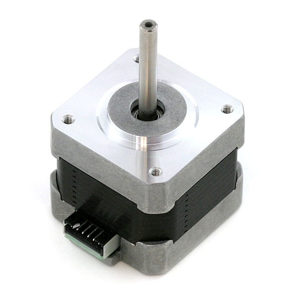
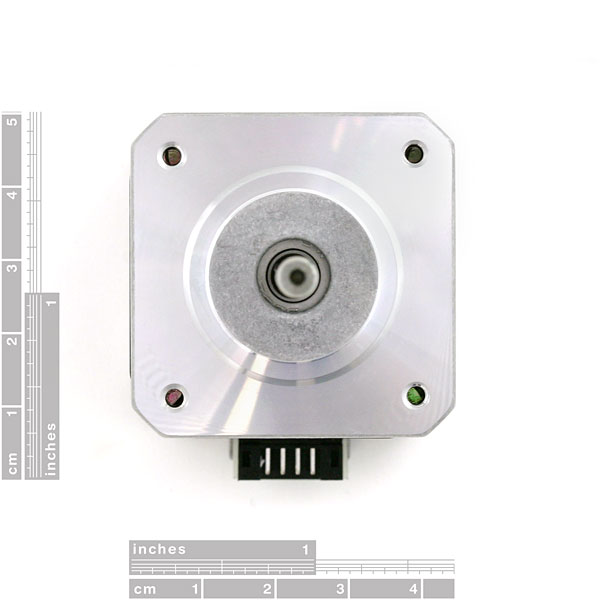
This is a simple, but very powerful stepper motor. You can make your own harness (2mm JST connector 455-1162-ND, crimp pins 455-1127-1-ND) or buy the wire harness sold below.
Note: The shaft length in the datasheet is incorrect, we are currently shipping shaft lengths of 62.5mm.
- Step Angle (degrees) :1.8
- 2 Phase
- Rated Voltage : 15.4V
- Rated Current : 0.28A
- Holding Torque : 2.4kg*cm
- Detent Torque : 120g*cm
- 5mm Diameter Drive Shaft
Comments
Looking for answers to technical questions?
We welcome your comments and suggestions below. However, if you are looking for solutions to technical questions please see our Technical Assistance page.
Customer Reviews
No reviews yet.


forgive the newb question.. but what is a good power supply to use with this?
it really depends on what voltage you will be driving it at. but 15V at 0.28A would be the max you need.
You can view videos of this motor in action as well as the easy driver and even an adapter for the shaft of this motor here.
Videos
Shaft adapter
You can view videos of this motor in action as well as the easy driver and even an adapter for the shaft of this motor here.
Videos
http://www.youtube.com/watch?v=sRIBZFlxGIw
http://www.youtube.com/watch?v=3SzWp0vVAzI
Shaft adapter
http://www.youtube.com/watch?v=UtKU1pipy7s
My youtube page
http://www.youtube.com/user/Halo2maniaccc
What have you guys used to attach the motor shaft to gears or threaded rods, etc? The one I got has a perfect rod for the motor shaft, and I'm worried a gear with a set screw would be overcome by the motor's torque...
Any thoughts?
Thanks,
Ben
Could someone clarify the shaft length note in the description? Is it 62.5 instead of the 33.8 on the datasheet, or is that a measurement from somewhere else?
You can try Trossen Robotics. They show this motor in stock and at the same price. They also seem to sell a lot of Sparkfun-made products too.
Though it will step at 12V, I have experimented with the motor and found it will not step accurately at anything under 12.6V. It advertises a +-5% error, though mine came with no error, so it took 1600 steps, at 1/8 microstepping, to do a full rotation. Mine would not do a full 1600 steps at under 12.6V.
I'd also like to be able to get a hold of a few of these myself. Thank you.
2nding this, please get some more of these in stock!
Hey all,
Just wondering when you will get more of these in, as these look like great little motors for the CNC I'm making.
If you won't be getting them in any time soon, could you recommend another supplier for this stepper motor as it has the perfect amount of hold strength.
Thanks.
SolidWorks model available here:
http://adam.theoherns.com/wp-content/uploads/2009/02/rob-08420_steppermotor.zip
Sketchup model.
http://sketchup.google.com/3dwarehouse/details?mid=d0dfff3a7c39ba603e0d0b5a1e930776
Question - I'm evaluating this motor and the datasheet says it is rated for about 15.4 VDC. I applied 12 VDC and stepped it through its phases - everything looked good.
I noticed that after leaving it powered for about 10 minutes, it was too hot to touch. Does this require a current limiter or voltage de-rating, or does it naturally run hot?
Mine wasn't accurate at 12V. See my comment below
Roughly speaking, you pass high(er) voltage through one coil to energize it, then pass power through the other coil and the rotor will advance one step. The extra 2 wires do not connect. The Arduino does not have enough power from its GPIO pins to do this directly. That's why stepper motor controller were invented - to handle the bigger power requirements.
Pardon my noob question... but I bought this to use it with an Arduino Diecimila and I'm able to run it by connecting it's 4 control pins to 4 digital outs on the Arduino. However, that leaves 2 pins remaining which I assumed I could attach to a 9V power adapter for greater torque... however attaching power doesn't do anything. Am I missing something huge? How do I connect power to this? The datasheet doesn't label those 2 other pins as + or -.
This is a bipolar motor, as evidenced by the schematic (two coils with only end connections and no center taps). It only utilizes the inner and outermost pins. The two other pins aren't connected to anything and applying voltage across them will not do anything. In fact, if both pins are connected to a common node (i.e. the housing) you may be shorting out the power source, which is not a good thing. If you want to increase the current through the coils you should either:
a) use a motor driver circuit (such as the one listed below)
-or-
b) connect the Arduino control pins to power transistors and use the transistors to switch a higher current source.
Hope this helps!