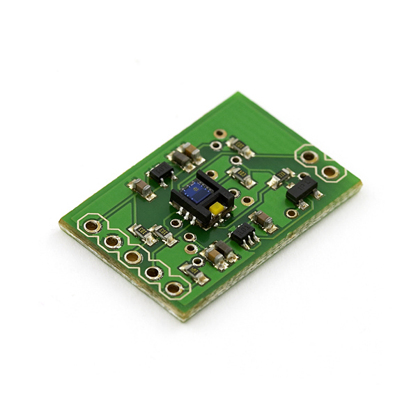
Color Light Sensor Evaluation Board
Replacement:SEN-10701. The ADJD-S371 is now obsolete, we are now offering a breakout board for the replacement IC. This page is for reference only.
The ADJD-S371 is a great little sensor. This evaluation board provides all the necessary support circuitry to actually play with the sensor!
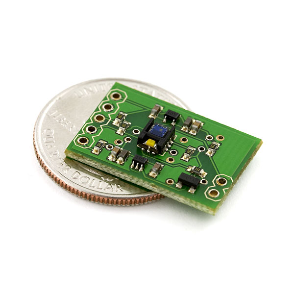
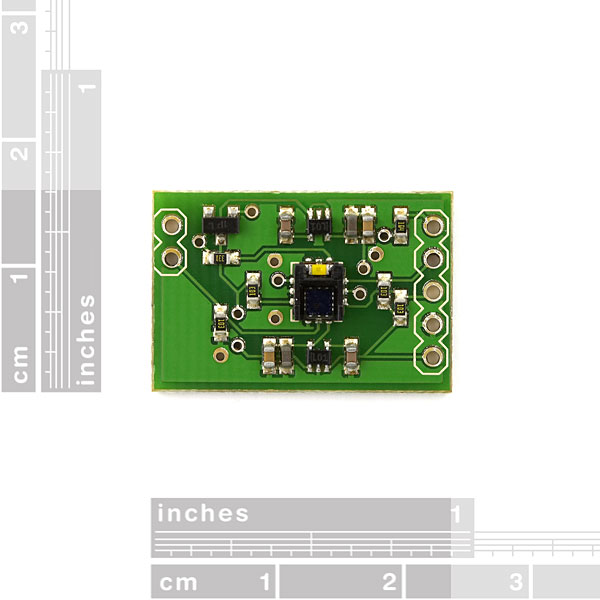
- 0.6x0.9"
Comments
Looking for answers to technical questions?
We welcome your comments and suggestions below. However, if you are looking for solutions to technical questions please see our Technical Assistance page.
Customer Reviews
No reviews yet.


I have tried using your code but it only keeps saying
read:64 or read:0
The lED is on but there is no reading
This breakout board is a great small little beast. I have compiled some code to use the ADJD-S371-Q999 with the Arduino.
does this breakout board include the sensor?
I would also like to know if this board actually includes the sensor with it?
Yes
afdf
I dont now how to use this colorsensor. I want to read regulary RGBvalues but this sensor cannot! This problem is colorlightsensor? or sourcecode? now, I using ADJD-311 colorlightsensor. but values very irregulary!! I really want to make regulary RGB data values!! but so very hard!! please anybody help me!! I researching this project but difficult. If anybody ok, please send my e-mail. send regulary RGBvaules. rosshild21@gmail.com here my e-mail source code and explain please!! I waiting….. thanks.
Can anyone tell me what my problem with this sensor might be. I have been programming it. When i write to the sensor the sensor will send back an acknowledgment bit saying that it understands, but when i read from it i only get eight high bits back. I'm wondering if i could have damaged that part of the sensor or what else it could be.
Anyone knows the part number of the voltage regulator on that PCB?
Does this board include the sensor?
I'm a EE rookie attempting to implement one of these for a project where a green LED (and its duty cycle) must be detected. That being said, I'm confused as to whether I can detect the incident light from the LED without using an LED to emit light? I basically just want to mount the board so that it is perpendicular to the top of the green LED, ignore all light other than green light, and let my micro know when green light is detected and what the duty cycle is.
Any info would be much appreciated, especially that pertaining to how to wire the board.
Snake,
You're not working on something for SECON, are you? ;)
I've ported Marcus' code to C# for the Netduino.
http://harfordhackerspace.org/2010/07/netduino-debut/
I plan to update this tutorial as I learn more.
If Avago is discontinuing this item, do you believe there will be a drop in replacement / new version? I want to make this part of a design I may sell a few copies of. The documentation for the calibration part is a bit convoluted, I am on an FPGA board, so I cant use the code people have posted.
If an item goes EOL we typically find a replacement for it. Sometimes it takes a while to get a replacement up and running though.
I've been designing something around this sensor, but if it's EOLing I really don't want to build on something that's not going to be around soon.
I have found the TAOS TCS3414CS which would be awesome to use (almost the same device), except it's chip-scale, like the ADJD-S311. Would it actually be possible to produce a board for that?
Would this thing be able to read the approximate color of the ambient light in a room, or would another component/circuit work better for something like that.
I know this is designed to read colors from objects upclose to the unit, but am wondering if it'd serve my purposes as well, as it's the closest thing I've found to what I'm looking for.
For that application, I'm guessing you'd want to disable the white LED and put some sort of neutral-color diffuser over the part (ping-pong ball?)
Hello everyone,
I think this board sensor can operate with 5V as well instead of 3.3V. I don't see any reason for damaging the hardware, because the 2.8V regulators can operate in a range 3.05V to 6V input if I am right... (see LP3987 data-sheet).
Please let me know of what you think!
Thanks
Akis
I bought one of those and it is working fine. I am wondering if I bought another one. how can I use both of them on the same I2C bus and they have the same Slave Address.
Any help would be appreciated.
Thanks.
I have the same problem. How I can change I2C address for use some modules?
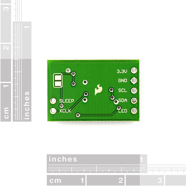
if there is another rev planned for this board, please break out the XRST pin.
I have a simple "firmware" for the sensor which responds to 'R' to read and 'C' to calibrate (whitebalance) via serial. It is lacking the code to ensure bright lights do not overflow the sensor, but since that is not a concern for me, it is an exercise for the reader :P
http://git.pictorii.com/?p=sketches.git;a=blob;f=colour_sensor_firmware/colour_sensor_firmware.pde;h=407aef314730a8890ccb926ef760b0447a1a989d;hb=HEAD
Simpat,
The problem is that Avago is planning on discontinuing this line of products at some time in the future. No official announcement of end-of-life yet, but it may come as early as mid-year.
Avago withdrew the product from its site ... problem?
I notice that the LED on my board is very dim. I've taken readings from the sensor with target media 3-5mm in front. But with the provided LED I have to jack the gain up to it's highest value to get any signal. It works fine with brighter light sources.
I'm trying to figure out if:
(1) My LED is busted
(2) My sensor is busted
(3) I'm screwing up calibration
(4) Everything is normal. I just need more light
Any help would be greatly appreciated. Thanks!
- Braden
I think I've found a problem with the design of this board, and an explanation for your low brightness. With the LED being driven by the transistor, and with the voltage drop across the transistor, we'll probably only be seeing about 2.6v across the resistor and the LED. I have used the avago color sensor without this board & I've had the LED running at about 6mA & it's very bright indeed. With this board the LED will probably be drawing less than 1 mA ( I haven't measured it, but I will soon ) and so we'll be seeing about a tenth of that (judging by fig 13 in the sensor's datasheet).
So I think this board needs a redesign. I was driving the LED directly from a logic pin just using a current-limiting resistor and I had no problems (and a very bright LED!).
So I finally got around the checking the LED voltage, and it is only being driven at about 1mA - not enough to really get much brightness. I'm going to mod my board and connect the LED logic pin directly to the 300 ohm current-limiting resistor, bypassing the transistor and the resistor on the transistor's base. This should give me 10mA or so (maybe less) and if your micro can source 10mA on a logic pin (the freescale micro I'm using can), then you should be fine.
Hi Buro,
I am puzzled by the design too,
as taking a look at the schematic, there is (R5) a 300 ohm resistor for +Ve. This sounds a bit heavy for connecting a white led to 3.3V:
- assuming about 3.2..3.6V drop for the white led + some 0.2..0.6V for the transistor we have something like 3.4..4.2V drop in components. And on top of this here is this the resistor that limits with 1.5V drop the current to manufacturer-recommended 5mA. To me this would seem that it as intended to be used with +5V power source, now way it should be workable with 3.3V.
With that 300ohm resistor it gets nicely about 5mA for the led. (assuming close-to-zero drop in the transistor)