Eagle Text Reference Board
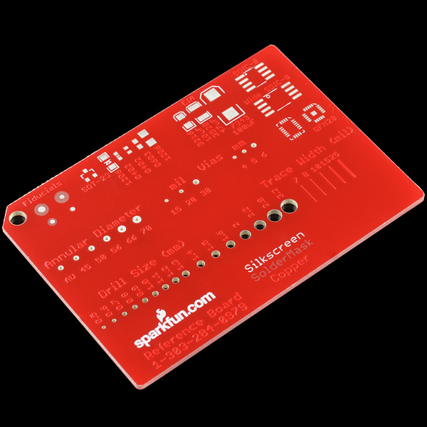
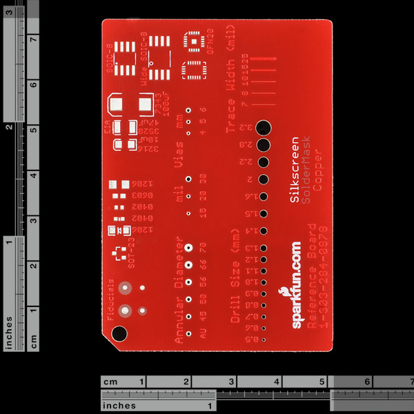
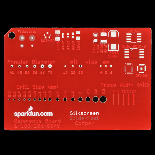
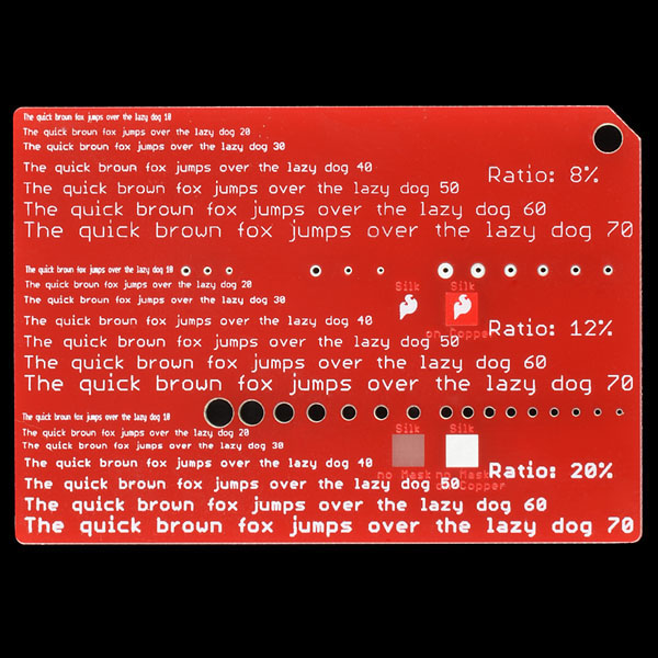
If you've ever played with Eagle PCB, you know that silk screen indicators are one of the most important aspects of your layout. We created this board to illustrate various text sizes and ratios (text width). You may use size 0.020 text with a ratio of 8% on your PCB layout, but as the reference board demonstrates, you really can't read it. We also included various drill sizes and trace widths but they are not completely accurate - the manufacturer increased the really small trace widths to avoid DRC violations. This is a great board to quickly determine the best size and ratio for text, drill sizes, and trace widths when creating your next design.
- 2.2x3"
Comments
Looking for answers to technical questions?
We welcome your comments and suggestions below. However, if you are looking for solutions to technical questions please see our Technical Assistance page.
Customer Reviews
4 out of 5
Based on 1 ratings:
Good for rough referencing
I keep this board in my wallet and it is a good buy if you use eagle. Use this board when you're designing something with Eagle (or Altium, etc.) and you want to put your traces, drills, etc. into scale. Only use this as a rough estimate, but not for exact measurements, because some measurements are a bit off. I've had this little thing for quite a while now and the bare metal has started to corrode a little. :/ Even thought there is a hole in the corner, it is still a bit too big for a key-ring, but it is almost a standard credit card size, so it will fit into your wallet. I like this thing a lot and it follows me wherever I go, and I can really say that this thing is a good buy.


This would be even more useful if it had some sample pads for SMD devices (0402, 0603, 0805, etc). And for the drills, an array of via diameters vs. drill size (so you can get a sense of the thickness of the annulus).
Good idea! I've updated the eagle files - I'll even throw them up here in a second. Pictures should be updated next week. The new rev has added pads, drill hits, fun stuff with the soldermask and such.
This reference is very helpful! I use it frequently, but I do have a couple of comments:<br />
<br />
-There are two 0402 pads (granted, one of them is for an LED but it doesn't show on the board) but there is no 0805.<br />
<br />
-The trace widths are not the default sizes in eagle (10, 12, 16, 24, 32). It's good that you show as small as 7 mil though.<br />
<br />
-The SOIC-8 is helpful. Is there room for MSOP and/or TSSOP packages?<br />
<br />
I hope that these suggestions can made a great product greater!
I just got mine, it is a great reference.
Still wish you would put solder mask around the traces so it would be easier to see just how wide they are. I'd add a solder mask that was about 5 larger than the trace.
Mine is so heavily covered with red solder mask that the copper side is unreadable. Very disappointing.
The traces examples on this board should have been bare copper, but they are all covered with solder mask. That makes it a bit less useful than it could be.
Pretty nice for a reference so I can show colleagues what's reasonable through the two services at our disposal. Agreed with others that this could be an even more complete reference for those doing more advanced things, though :)
Very good reference! I showed it around. You will be getting more orders for this!
BTW: Wish there was a 20 mil trace. I use that for most of my power lines.
Hi, very nice board, but unfortunately the eagle source files zip file is corrupt when i download it using ie8
Regards, Hans
I was shocked when I saw this item listed. I could have used one of these a long time ago. I can't wait until I can get one for myself.