Graphic LCD 160x128 Huge
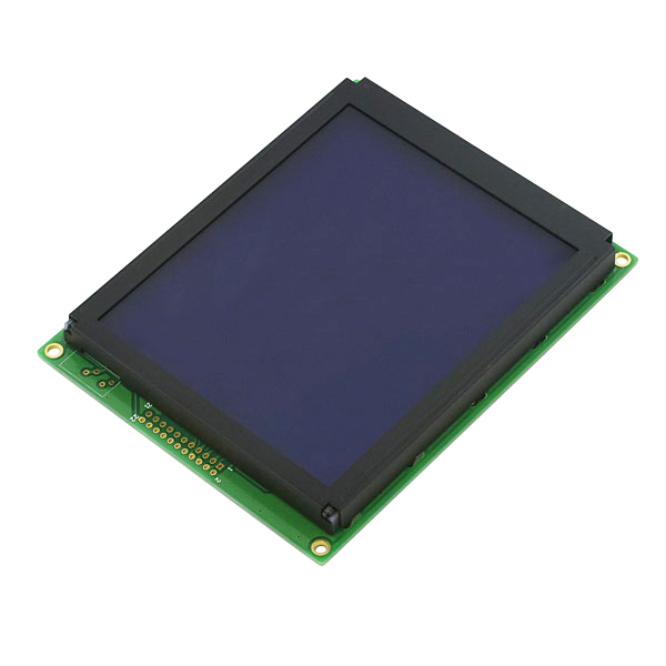
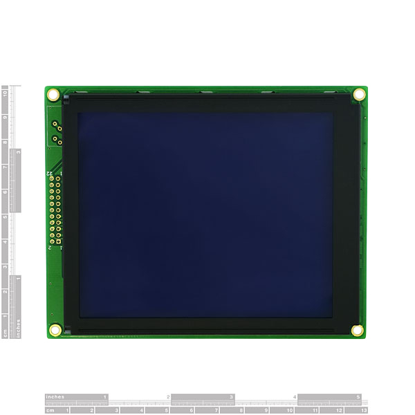
This is a big, really big 128x160 pixel graphical STN LCD. The LCD has a blue background and pixels appear white. Unit comes with an LCD backlight and built-in parallel interface controller. LCD and backlight are driven by 5V (negative voltages for contrast are generated on-board).
- 160x128 pixel
- STN Negative Transmissive
- Blue background, white pixels
- 1/9th Bias
- White LED backlight
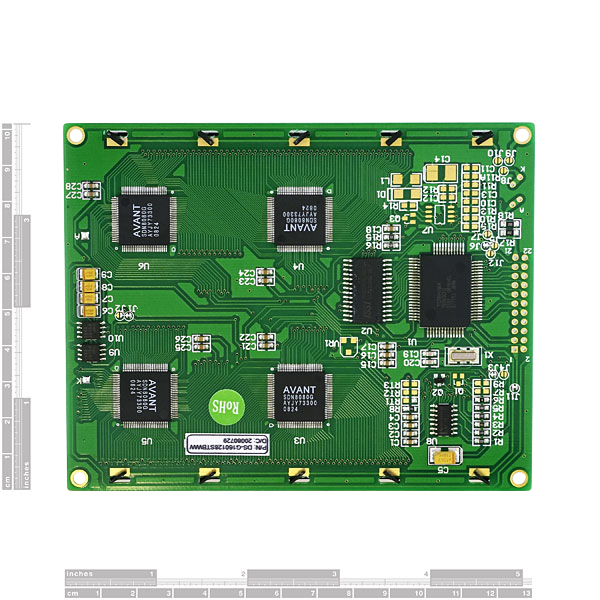
- T6963C Controller
- LCD: 5V@1mA
- Backlight: 5V@200mA* 4x5" (102x129mm)
- 0.57lbs (260g)
Graphic LCD 160x128 Huge Product Help and Resources
Core Skill: Soldering
This skill defines how difficult the soldering is on a particular product. It might be a couple simple solder joints, or require special reflow tools.
Skill Level: Noob - Some basic soldering is required, but it is limited to a just a few pins, basic through-hole soldering, and couple (if any) polarized components. A basic soldering iron is all you should need.
See all skill levels
Core Skill: Programming
If a board needs code or communicates somehow, you're going to need to know how to program or interface with it. The programming skill is all about communication and code.
Skill Level: Rookie - You will need a better fundamental understand of what code is, and how it works. You will be using beginner-level software and development tools like Arduino. You will be dealing directly with code, but numerous examples and libraries are available. Sensors or shields will communicate with serial or TTL.
See all skill levels
Core Skill: Electrical Prototyping
If it requires power, you need to know how much, what all the pins do, and how to hook it up. You may need to reference datasheets, schematics, and know the ins and outs of electronics.
Skill Level: Competent - You will be required to reference a datasheet or schematic to know how to use a component. Your knowledge of a datasheet will only require basic features like power requirements, pinouts, or communications type. Also, you may need a power supply that?s greater than 12V or more than 1A worth of current.
See all skill levels
Comments
Looking for answers to technical questions?
We welcome your comments and suggestions below. However, if you are looking for solutions to technical questions please see our Technical Assistance page.
Customer Reviews
4.6 out of 5
Based on 5 ratings:
160x128 lcd
Good service and good lcd.
Great LCD
Great LCD, clear display and easy to use
Product is as described!
Very Large display! Excited about applying this display. The data required to integrate the display is all available on the Sparkfun WEB site. Good Work Sparkfun.
Very pretty, but refreshes slow.
I am going to go with this one again for my next big stompbox control unit. I need something that displays characters that are easy to read from six feet away... and this does that very well.
What it doesn't do for me well, is refresh large characters quickly. It may be exacerbated by the only driver on the OBEX for the Propeller MCU being slow (or is it?). It seems to refresh small characters in less than a second... the large font takes twice as long.
If it just refreshed quickly, it would be amazing. As is, it is pretty good for displaying raw data that doesn't change often. Any suggestions from other users would be welcome.


Sure it can be used in "portrait" mode. It's a SMAP - small matter of programming. You just have to do the work of turning everything 90 degrees. You won't be able to use the built in fonts, though. Not hard to do but a bit tedious.
I got it to work with a Propeller 3.3V MCU with I/O pins connected directly, even though it's a 5V device.
There are errors and misleading notes in the documentation...
I've made my own notes on it here:
http://www.rayslogic.com/propeller/3rdPartyHardware/3rdPartyHardware.htm
The DiStar datasheet is pretty basic on the capabilities of this device. Download the datasheet for the Toshiba T6963 controller to understand all the device features and how to program the interface correctly.
This device uses a 32KB static RAM and a 8x8 character generator ROM. Text pages are 20 columns by 16 rows (320 bytes) The RAM can hold several text and graphics pages and these can be selected by changing the base address in display RAM memory.
It's also a neat clear display!
Took me while to work up the courage, but I finally just connected the HALT pin directly to Vdd 3.3v. It seems to be working fine. I didn't see anything anywhere about what to do with this pin, so I just guessed.
What kind of controller would I need, so that I can display Voltage input/output, Current input/output, Speed, Odometer, and Battery Life. I'm a novice and would really appreciate some help in this venture.
This LCD is kind of lame. In the T6963c datasheet, you will read that the char generator will produce either a 6x8 or 8x8 font depending on the FS pin. This LCD has the FS pin fixed on the PCB somewhere to 8x8. Now, the problem is that it really doesnt give you a 8x8 or 6x8 font, its only 5x7. That is a 5x7 char in either a 6x8 space or 8x8 space. Sooo... this means that the since this LCD has the FS pin wired to give "8x8 font", your text has a bunch of extra spacing between chars which looks **RETARDED **. Very misleading.
Can anyone please measure the diagonal distance from top left pixel to bottom right pixel? Doesn't have to be exact, of course, within a millimeter or so.
Thank you very much
how to configure this in Bascom avr lcd and that I can not set 160x128 T6963C
I recently picked this LCD up and started playing around with it. I'm using a dsPIC30F4011 to control it, and its works great. It has a mode where you can just run the LCD like a character lcd, so it runs in a 20x16 character setup. I'm using it as the main display for a system I'm building.
The app note is pretty straight forward, just follow the steps in it and you'll be good to go.
Cobalt,
Would you mind putting up your C code (if you're using C) for initialization of the LCD? I'm going to be using a dsPIC30F6014A. Thanks.
does any one know anything about where fs is on this display i see it in the block diagram and in the T6963C datasheet but not in the pin out,
any info. would be greatly appreciated
Anyone know how to wire this thing to an Arduino Mega?
Hello, can anyone post a picture of this display using blue characters on the white background ?
Also, does this display get warm with the powerful backlight (1W!) ?
Does anyone know if this display can be used in a "portrait orientation (i.e. 128x160) ?
Cheers,
- Nick
JB: Sorry, I just noticed your question (I don't look here very often!)
I am powering the display with 5V. I don't think it would work with 3.3V power, but I don't remember if I tried that or not...
rayman: when you connected it to a 3.3V interface, did you give it a 3.3V Vss also?
It seems to have a pair of FG/FS pins; FG is documented as frame ground. But I don't see FS documented - do I need to worry about this?
I'm hoping to use it with a 3.3V LPC2294 via the EMC CS2.
I'm assuming the backlight is a totally separate circuit and I can use an external DC supply for that...
Oops, obviously I meant to ask if you used a 3.3V Vdd also...
guys if anoyne has gotten this display to work with a stamp or pic or anyhting and you are willing to share your methods could you please email me, I have had no luck what so ever getting this to work I have tried the prop chip and a basic stamp but I am stumped thanks mikediv@comcast.net
Could anybody comment on how bright this LCD is? Is it bright enough to be used outside?
Greyscale
I've had similar problems, but at long last I can get the screen to clear command to work succesfully. I haven't gotten any text or GFX to work - but I haven't picked it up in about 2 weeks. The method I used was going through the assembley code provided in the distar datasheet line by line and translating it to my hardware and into C (C18 pic complier).
I took Malcolm's advice and got the datasheet for the T6963 and found that more helpful. I'm really trying to get my code to a functional point - the display looks great, unfortunatley it is a bit finky to program. What approach are you taking to programming the screen.
I cannot for the life of me get this LCD to work. It also has an odd /CE (Chip Enable) pin and an odd /Halt pin. I've been using a PIC16F874a and I cannot get it to display any damn thing, nomatter how much I coax it. :/