RCA Jack Breakout
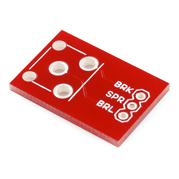
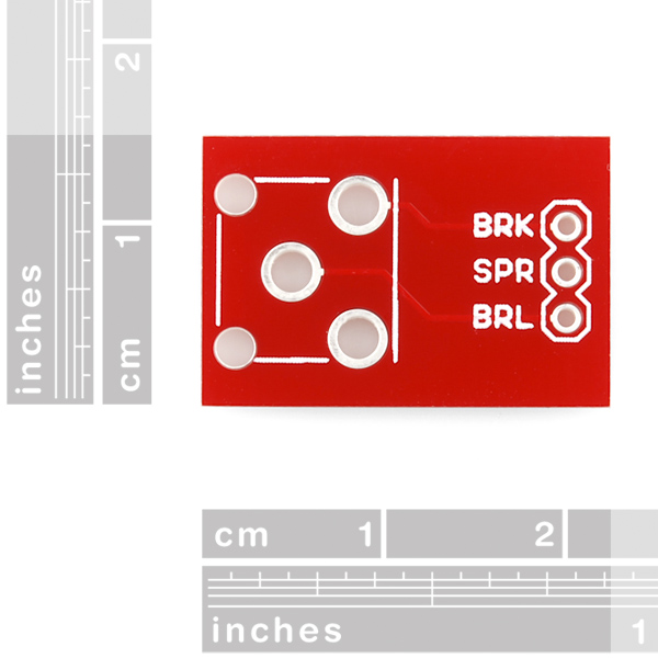
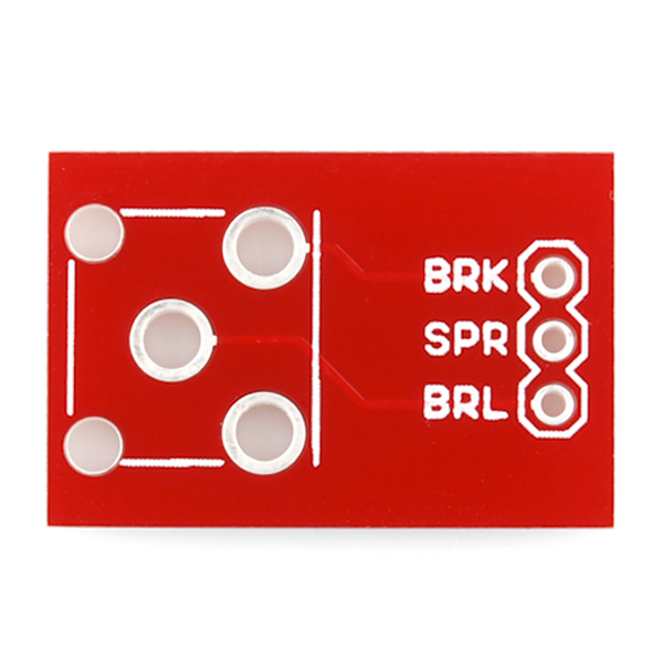
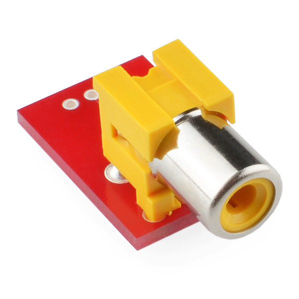
Simple breakout board for the RCA connector. Use this breakout (shipped bare) to allow breadboard or SIP access to the super-common RCA video/audio jack. All three pins are broken out.
Bare PCB only
Documents:
RCA Jack Breakout Product Help and Resources
Core Skill: Soldering
This skill defines how difficult the soldering is on a particular product. It might be a couple simple solder joints, or require special reflow tools.
Skill Level: Noob - Some basic soldering is required, but it is limited to a just a few pins, basic through-hole soldering, and couple (if any) polarized components. A basic soldering iron is all you should need.
See all skill levels
Comments
Looking for answers to technical questions?
We welcome your comments and suggestions below. However, if you are looking for solutions to technical questions please see our Technical Assistance page.
Customer Reviews
No reviews yet.

Why was this retired? It's a real shame that you're on a trend of retiring all the useful general purpose stuff in favor of releasing complicated boards that have only very specific uses. Simple things like this RCA breakout were always the majority of what I ordered from SparkFun.
Looks like this just wasn't selling well. That may have to do with RCA not being used as much in things anymore. We definitely like to have a combination of different types of boards because you often need the simple boards to use the more complicated ones. We are still selling the jack and feel free to use a service like OSHPark to order a few PCBs.
Thank you for your reply, M-Short. Greatly appreciated.
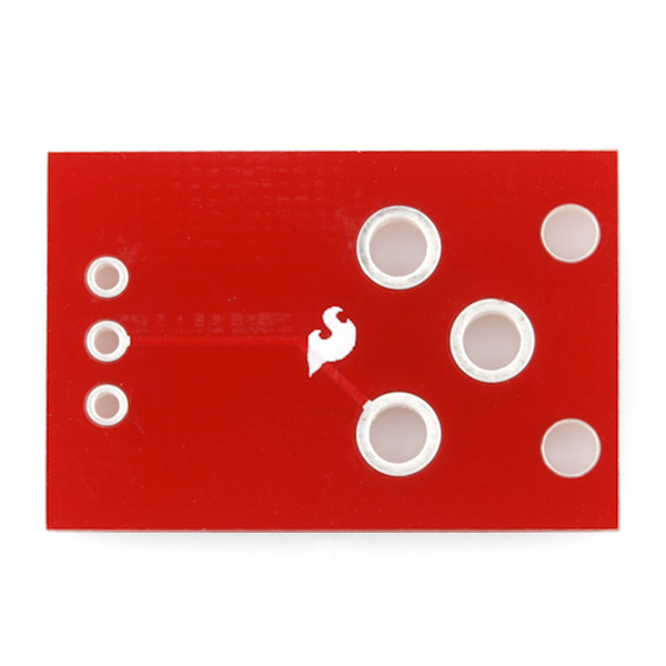
Hey guys.... your RCA jack is upside down in the last picture. Shouldn't it be on the other side?
Cheers,
baum
Why three pins? And where did you get BRL, SPR, and BRK from? I guess BRL is barrel, and thus ground. The middle plug (signal) has continuity with SPR. so is BRK the switch? But what are these names? Is SPR "spear"?????
The schematic uses the terms break, spring, and barrel.
Still no idea where the names came from, but to replicate Crono's comment: BRL to ground, BRK to signal. SPR, on the other hand is tied to BRK (signal) when disconnected, and left floating when connected! Can anybody see the flaw in this (sarcasm)? Isn't it standard, for example, in DC barrel jacks, to have the switch go to ground? With the switch going to signal, it will be VERY hard to tell whether or not it is plugged in. Or am I mistaken?
I believe that the purpose of such a layout would be to send the video or audio signal elsewhere in the circuit (maybe a coaxial converter) if nothing is plugged in.
So, the SPRing pin is connected to the BaRreL pin while there's no cable connected to the jack, and disconnected when we connect a cable in the jack. Did I understand what you're saying?
Please provide the EAGLE layout for this RCA jack footprint (not necessarily the breakout board). I saw no RCA in the current SparkFun library. Maybe I'm missing something. I should have gotten out the calipers to check the footprint I used before sending a proof board to BatchPCB.
In the library it's under POWER_JACK. The actual footprint & schematic seems to be POWER_JACKRCA. There's also POWER_JACKRCA_LOCK.
For anybody using these breakout boards... BRK is the signal, BRL is Ground. If your attaching these to a CMOS camera make sure that BRL shares a common ground with your camera.
Are the BaRreL and SPRing connections connected to each other in the RCA jack?
Dare I mention that I found that one out using a connector that wasn't mounted on that style break out board?