Mini Button Pad PCB
Replacement: None. We don't sell the button pads to match these any longer so it doesn't make much sense to keep on making these. This page is for reference only.
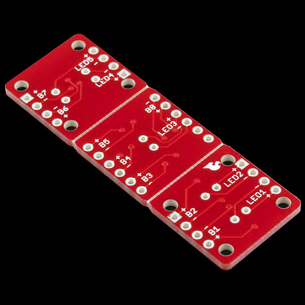
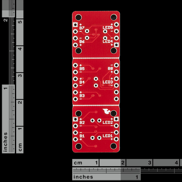
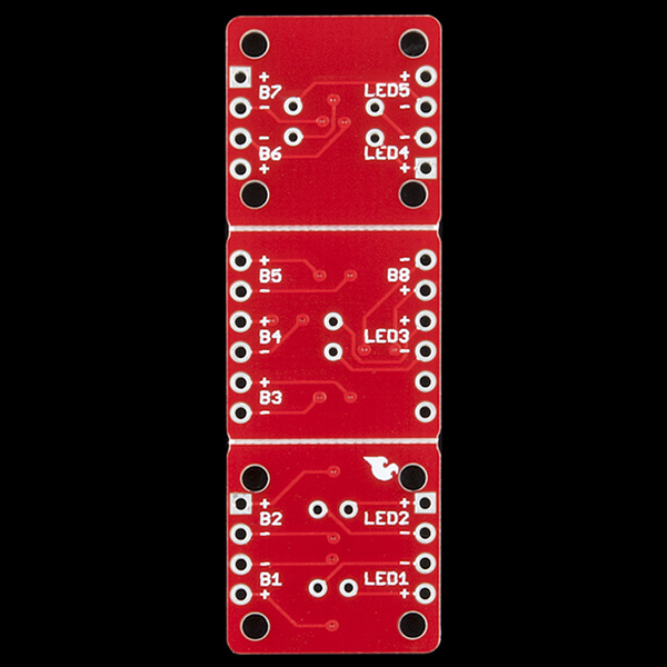
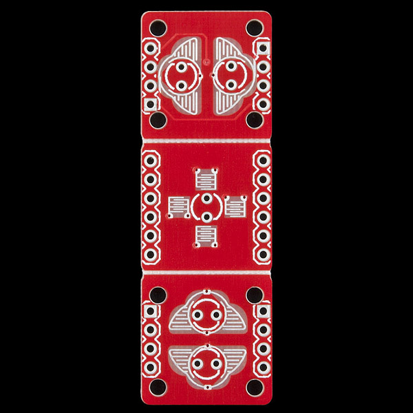
This is a specially designed PCB that works with the silicon button pads, bezel, and mounts easily into a project enclosure! The PCB accepts 3mm LEDs and 0.1 inch headers for connections.
The PCB can be separated into 3 different button configurations or used as is. Each button configuration has 4 mounting holes located in each corner for sturdy mounting in any enclosure. The center button is directional, so an up, down, left, or right push will toggle the breakout pins, see schematic for more details.
Note: This is only the bare PCB. Please see the related parts below for hardware and compatible components.
Comments
Looking for answers to technical questions?
We welcome your comments and suggestions below. However, if you are looking for solutions to technical questions please see our Technical Assistance page.
Customer Reviews
No reviews yet.


The pads for these are sold out, we only have the PCBs left.
Sold out for ever?
Same ? as gripen40k - where are the pads?
Same here, I bought some of these pads a while ago, need more, where are they Sparkfun? Please reply?
Same here - any news on the pads please?
Are the silicon buttons for these unavailable? I can't find them anywhere on the site and they don't show up at the bottom for me...
Pros:1. Interesting Concept,4 way button on the middle button.
2. Back lit buttons.
3. Pre-Drilled for mounting. (see Cons)
4. Snappable for 3 separate button groups (see Cons)
Cons:1. Only fits micro led's & maybe sm-leds.
2. Header holes proximity to button pads. (Capillary action when soldering.)
3. Mounting holes proximity to header holes, Possible Ground fault depending on housing.
4. 4 mounting holes for the 2 outer buttons but none for middle 4 Way button.
5. The Snappable design creates a weak spot, even when the Board is mounted the middle piece will break after a few firm presses which is normally needed for buttons of this type.
so are there mounting holes on the middle section? none in the pictures
I would like to use these on my own PCB board. I see you use U1-U8 devices in the schematics. What are they called in eagle library?
The holes drilled in the PCB are to close to the header holes, the screws included (when turned either way) will hit the header plastic if one is installed.
Is the middle button usable as a Joystick/ 4-Directional button?
You can use 4 directions on the middle button. The results are decent but not always perfect because of the small size of the button.