Basic 16x2 Character LCD - White on Black 3.3V
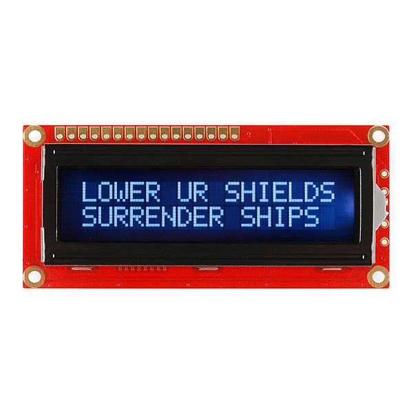
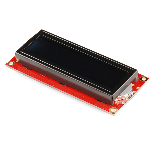
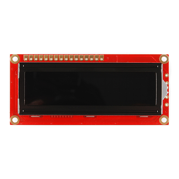
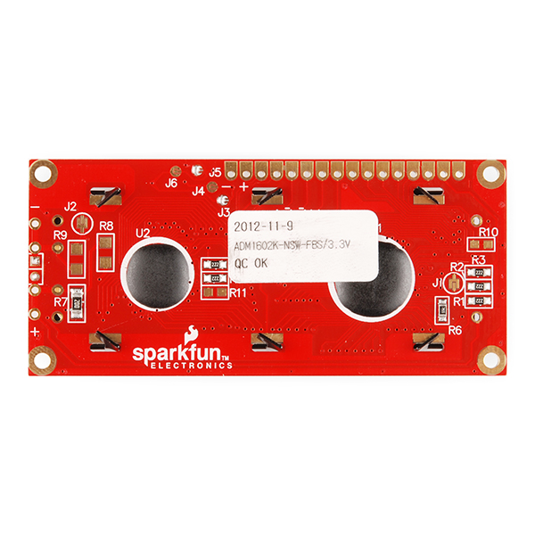
This is a 16 character by 2 line display that runs at 3.3V. Utilizes the common ST7066/HD44780 parallel interface (datasheet). Interface code is widely available for many different controllers and systems. You will need ~11 general I/O pins to interface to this LCD screen. Includes white LED backlight.
- High quality STN 16x2 character LCD
- 3.3V power supply
- White LED Backlight
- 5x8 dot characters
- ST7066 controller
- 1/16 duty cycle
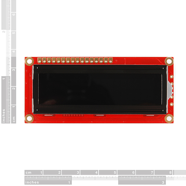
- 0.34 x 1.4 x 3.2" (8.6 x 36 x 80mm)
Basic 16x2 Character LCD - White on Black 3.3V Product Help and Resources
PIC-Based Serial Enabled Character LCD Hookup Guide
May 29, 2018
The PIC-based serial enabled character LCD backpack is a simple and cost effective solution for interfacing to character Liquid Crystal Displays (LCDs) based on the HD44780 controller. The backpack simplifies the number of wires needed and allows your project to display all kinds of text and numbers.
Basic Character LCD Hookup Guide
May 28, 2019
Liquid crystal displays (LCDs) are a great way to output a string of words or sensor data to a display for visual feedback. In this tutorial, we'll learn about LCDs, how to print a string of words to a 16x2 basic character LCD and create custom characters.
Core Skill: Soldering
This skill defines how difficult the soldering is on a particular product. It might be a couple simple solder joints, or require special reflow tools.
Skill Level: Noob - Some basic soldering is required, but it is limited to a just a few pins, basic through-hole soldering, and couple (if any) polarized components. A basic soldering iron is all you should need.
See all skill levels
Core Skill: Programming
If a board needs code or communicates somehow, you're going to need to know how to program or interface with it. The programming skill is all about communication and code.
Skill Level: Rookie - You will need a better fundamental understand of what code is, and how it works. You will be using beginner-level software and development tools like Arduino. You will be dealing directly with code, but numerous examples and libraries are available. Sensors or shields will communicate with serial or TTL.
See all skill levels
Core Skill: Electrical Prototyping
If it requires power, you need to know how much, what all the pins do, and how to hook it up. You may need to reference datasheets, schematics, and know the ins and outs of electronics.
Skill Level: Competent - You will be required to reference a datasheet or schematic to know how to use a component. Your knowledge of a datasheet will only require basic features like power requirements, pinouts, or communications type. Also, you may need a power supply that?s greater than 12V or more than 1A worth of current.
See all skill levels
Comments
Looking for answers to technical questions?
We welcome your comments and suggestions below. However, if you are looking for solutions to technical questions please see our Technical Assistance page.
Customer Reviews
4 out of 5
Based on 3 ratings:
1 of 1 found this helpful:
16 by 2 @ 3V
It's really nice to be able to use an LCD display with lower-voltage development boards with no hassle about signal levels. Though I prefer to power my displays from a separate rail, it's no big deal, since the low-voltage boards usually run off 5V anyway. Thank you for offering a 3V version of this classic visual output device!
4 of 4 found this helpful:
Works well but needs better pin identification
At first I couldn't get it to work, then as I dug around the arduino.cc tutorials I noticed in the graphics they had that the board was rotated 180° from how I was attempting to use it. I had interpreted the - and + symbols on the board as being ground and Vcc respectively, going off of Peter Fleury's webpage linked in the article, when in fact they were actually the backlight LED cathode and anode (respectively). For anyone who might have less technical knowledge than me, I'll simplify this paragraph by saying that the LCD screen's letters rightside-up have the pins above them, and said pins are numbered increasing left to right, so that if you number the screw-hole closest to the pins as 0, the rest work out correct in accordance with Peter Fleury's page, with the addition of pins 15 and 16 as backlight LED + and - respectively
Also I'm curious to know how consistent the contrast-voltage-to-actual-contrast ratio is so I'll share that my LCD screen works close to best with a 0V - 820Ω - Vcontrast - 3300Ω - 3.3V voltage divider setup.
Also also, when Sparkfun says you'll "need ~11 general I/O pins to interface to this LCD screen" that doesn't account for the fact that you mostly don't need to "read" data from an LCD display and that it works fine for everything I've tried it out with in 4-bit mode, so you really only need Register Select (R/S pin 4), Enable Clock (E pin 6), and Data 4-7 (pin 11, 12, 13, 14), with Read/Write pin 5 driven to ground which adds up to 6 pins, 8 including ground and 3.3V. I've found it quite useful that it can be run entirely over a spare ethernet (8P8C RJ-45 tested with Cat5e) cable with the proper breakout boards.
Easy to use and works great at +3.3V
This LCD works pretty good, and truly works at +3.3Vdc very clearly. I have it in use with an I2C backpack and it makes its use super easy. I have the LCD by itself drawing about 1.5mA without backlight and 18.4mA with backlight. You can't really see the display without the backlight so backlight OFF is really a lower power state but nothing more.

This is incorrect:
"You will need ~11 general I/O pins to interface to this LCD screen."
The datasheet says otherwise.
I've run a pin-compatible controller over a 4-bit interface, using this fine gentleman's code:
http://www.avrfreaks.net/index.php?name=PNphpBB2&file=viewtopic&p=281379#281379
Only 7 I/O ports are required.
Also, to answer Crizo's question, no external resistor is required. There's a 25 ohm resistor on the LCD which does this for you. Just hook it up to Vcc (or through a MOSFET, connected to an 8th I/O port.) I think that this choice is unfortunate, because it eliminates the possibility of more efficient switching regulation.
Great LCD and easy to use!
I am trying this display on my Arduino. I hooked up the power and LED light power to the 3.3V, and the data,e,rs,etc lines to the digital outputs. The contrast is done with a poti. I wrote up some testing code that should just print one line, wait a second, clear and print a different line. The funny thing is, the contrast changes dramatically depending on what is being displayed, to the point where I initially thought one line wasn't being printed at all and the other one was. Has anyone had a similar problem with this display?
There seems to be a minor error in the ST7066 datasheet. On page 8, the 'Function Set' command shows that DB3 indicates the number of lines (should be set to 1 for this display) and DB2 indicates the font size (should be set to 0 for this display). This is correct and matches the HD44780 spec.
However, there is a problem on page 20 in the 4-bit interface example. In the 'Function Set' step, the document is showing these as the second nibble of DB5 and DB4, which correspond to DB1 and DB0 in 8-bit mode. This is wrong. It should be the second nibble of DB7 and DB6, i.e. '0 0 N F 0 0' rather than '0 0 0 0 N F'.
They get it right in the 8-bit interface example on page 19.
Can someone confirm that I am reading this correctly?
TO CREATE YOU OWN SERIAL LCD FROM ANY GENERAL LCD visit this link
http://www.circuitvalley.com/2011/12/two-wire-serial-lcd-16x2-graphics.html
I've got this display and I'm attempting to use it in a reverse geocaching puzzlebox. It's attached to a Mini Pro, so the voltages are at the right level, but I can't get the contrast right. I've tried a variety of resistors (10k,15k,22k) in combination with a 10k pot, yet I always have to turn the pot all the way up and the contrast is still poor.
Is it just that these 3.3V versions have poor contrast, or is there something else I can try?
Thanks,
Ray
Just put a ~ 1K resistor between V0 and GND, that should do the trick. I was strugling with the contrast too, following the datasheet and putting two 10K resistors between V+ - V0 - GND. That will give you very poor contrast indeed.
Milan
This a great little LCD and looks a lot cooler than the boring black on green flavor LCDs. And it runs on 3.3V (great for us PIC32 users).
Aha! This is the ST7066-0A version, which includes English and Japanese characters. Make sure you look at the character set specified on page 10 of the ST7066 data sheet and not page 11. The latter character set is the English/European version (for the ST7066-0B). It's too bad really, the second set has all the french characters I needed on top of a ton of other fun characters such ?, ?, ?, and so on.
deleted
Hello,
I try to connect this lcd to an arduino 2009? without success :(
Up to now, I connected both power pins and led backlight to 3.3V (following the datasheet)? but I'm wondering what is the output voltage of arduino pins. So the question is: can I use a 3.3V lcd display with an arduino or shall I use 5V displays only?
By the way, can I replace the potentiometer between Vss and V0 by a 15k resistor?
Thank you in advance for your help.
Thomas
Reading the datasheet for the LCD:
Input Voltage (VDD): Min: 3.1V Typ: 3.3V Max: 3.5V
"H" Level Input Voltage: Min: 2.2V Typ: - Max: VDD
From Arduino Duemilanove page, under "Input and Output":
"Each of the 14 digital pins on the Duemilanove can be used as an input or output ... They operate at 5 volts." (emphasis mine)
However, looking at Arduino Pro page, under the same "Input and Output" section:
"Each of the 14 digital pins on the Pro can be used as an input or output ... They operate at 3.3 volts." (again, emphasis mine).
The above bit for Pro doesn't mention if it's 5V for the 5V version, but if you're using the 3.3V version of the Pro, it stands to reason that it will at least run its digital I/O pins at 3.3V instead of stepping it up to 5V.
I hope this helps, and didn't come too late.
Normally we work with 5V versions, as most microcontrollers also use this voltage, any idea what the max input Voltage is for the 3.3 v version?
Maybe I'm missing it on the datasheet, but I can't find the backlight voltage or current specifications for the 3.3v versions. I'm trying to calculate the current limiting resistor value.