Gyro Breakout Board - IDG500 Dual 500°/s
**Replacement: **None. Unfortunately, the IDG500 has been discontinued, so there's no way we can make this board anymore. We'd love to, but we just can't. This page is for reference only.
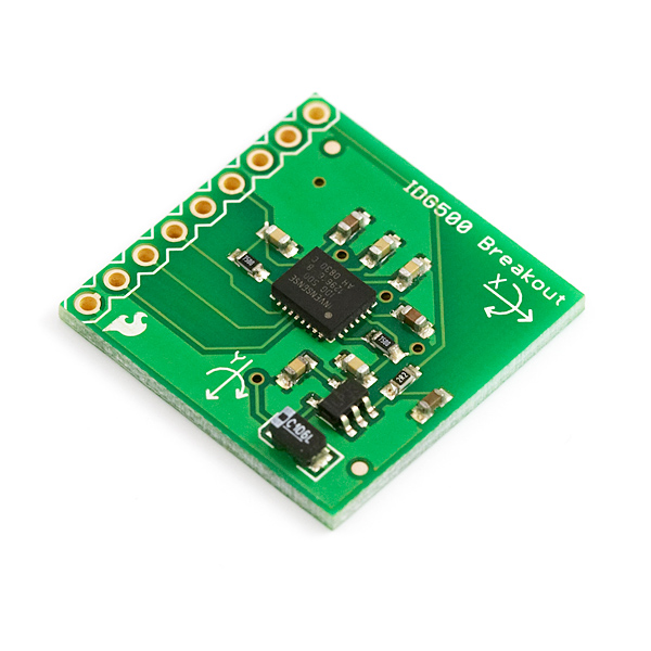
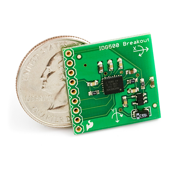
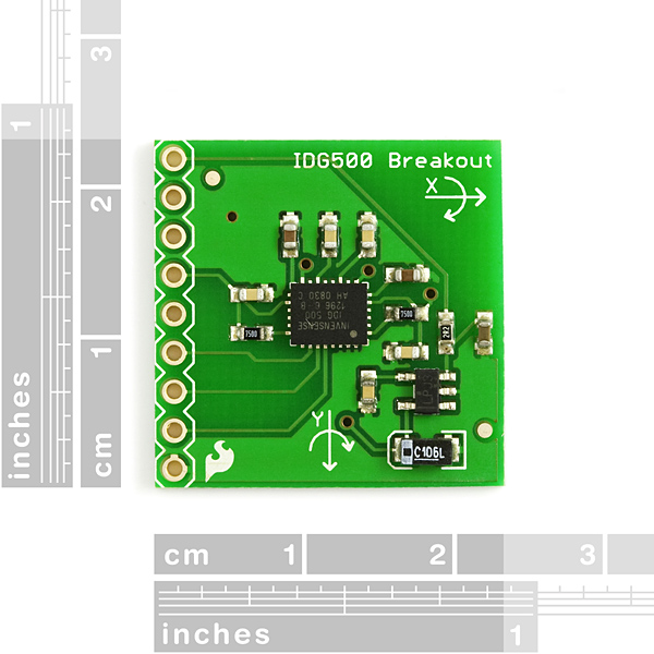
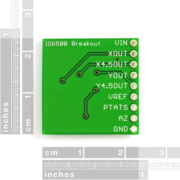
This is the breakout board for the IDG500, which includes an on-board 2.8V regulator and all pins broken out to 0.1" pin holes. The IDG-500 is a very small, dual-axis angular rate sensor (gyroscope). It uses InvenSense’s proprietary and patented MEMS technology with vertically driven, vibrating masses to make a functionally complete, low-cost, dual-axis angular rate sensor. All required electronics are integrated onto a single chip with the sensor.
The IDG-500 gyro uses two sensor elements with novel vibrating dual-mass bulk silicon configurations that sense the rate of rotation about the X- and Y-axis (in-plane sensing). This results in a unique, integrated dual-axis gyro with guaranteed-by-design vibration rejection and high cross-axis isolation. It is specifically designed for demanding consumer applications requiring low cost, small size and high performance.
The IDG-500 gyro includes the integrated electronics necessary for application-ready functionality. It incorporates X- and Y-axis low-pass filters and an EEPROM for on-chip factory calibration of the sensor. Factory trimmed scale factors eliminate the need for external active components and end-user calibration. This product is lead-free and Green Compliant.
Not sure which gyro is right for you? Our Accelerometer and Gyro Buying Guide might help!
- 3-7V single-supply operation
- Integrated X- and Y-axis gyros on a single chip
- Two separate outputs per axis for standard and high sensitivity:
X-/Y-Out Pins: 500°/s full scale range 2.0mV/°/s sensitivity
X/Y4.5Out Pins: 110°/s full scale range 9.1mV/°/s sensitivity - Integrated amplifiers and low-pass filters
- Auto-Zero function
- On-chip temperature sensor
- High vibration rejection over a wide frequency range
- High cross-axis isolation by proprietary MEMS design
- Hermetically sealed for temp and humidity resistance
- 10,000 g shock tolerant
Comments
Looking for answers to technical questions?
We welcome your comments and suggestions below. However, if you are looking for solutions to technical questions please see our Technical Assistance page.
Customer Reviews
No reviews yet.


When using the 4.5 times amplifier like this schematics does, one should connect the AZ pin to the ground in order to get the specified 2mV/deg/sec and 9.1mV/deg/sec. Otherwise the low internal pull-up on the AZ pin somehow influences the measurement giving you approximatively a 2.55 times reduced gain. (Confirmed at Invensense)
iam having a problem in gyroscope it is giving too much offset and having a problem that after giving a shock to gyro then at at stationary position the reading is deviating too much sometimes it is 1.04 sometimes it is 12.04............... does it means that my gyroscope is no more in working condition??
when iam not using 4.5put is it necesary to connect az or vref ? can anyone help me out ?
Sorry for the delayed reply. Since the AZ pin is designed to work with the 4.5output, you don't need to connect it if you are not using that output. See the Wiring Example linked above.
If I am not using the AZ input for the gyro, do I pull this input low?
hi,
i got an idg500 sensor and i want to use it to measure an angle. i connected it on a shaft and i want to see the difference between first and last position of the shaft. i am using labview program. is there anyone to help me?
How do you properly secure this on the chassis/board of the robot?
I'm thinking about ordering one, I have 2 ideas on how to fixate them, but they are both meh.
We find that most headers provide enough support to hold a board of that size in place.
Hi,
do I have to autozero only once before I use the 4,5 out?
Or do I have to autozero all the time?
How about adding a LISY300AL to this board?
And better, a 3 axis accelerometer!
That would make a new 6 DOF breadboard to be interfaced with the logomatic, a GPS and an XBEE to control a SparkFun UAV...
I would suggest to add the ISZ500 that has identical characteristics. And maybe something like the LIS344ALH ...