SparkFun Single Axis Accelerometer Breakout - ADXL193 (+/-250g)
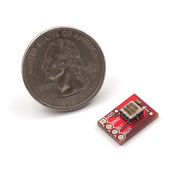
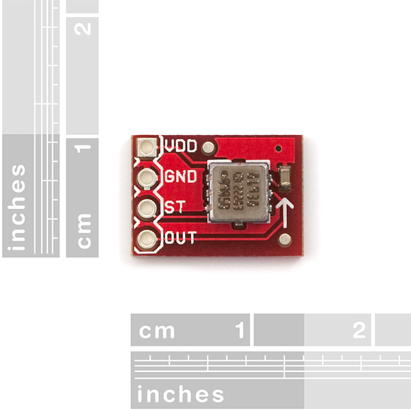
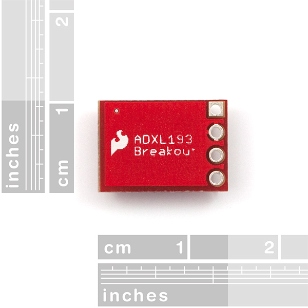
Breakout board for the low power, single axis ADXL193 MEMS accelerometer. The ADXL193 is a high-g sensor with a full scale range of ±250g! The ADXL193 can be powered from 3.5-6V. Access to the self-test pin is also provided.
Note: The ADXL193 outputs an analog voltage. This voltage is in ratio to the measured acceleration and to the supply voltage. You will need some extra hardware to convert this analog signal to a usable digital one. Luckily, many uCs have a built in Analog to Digital converter.
- Sensing Range: ± 250g
- Output Signal: Analog (ratiometric)
- 0.4x0.55"
- [ Schematic](http://cdn.sparkfun.com/datasheets/Sensors/Accelerometers/ADXL193 Breakout-v11.pdf)
- [Eagle Files](http://cdn.sparkfun.com/datasheets/Sensors/Accelerometers/ADXL193 Breakout-v11.zip)
- Datasheet (ADXL193)
SparkFun Single Axis Accelerometer Breakout - ADXL193 (+/-250g) Product Help and Resources
Calibration
This is a high-G accelerometer. It won't be too accurate if you use Earth's gravity to calibrate this sensor like the other low-G accelerometers on our site. The best would be to use some specialized equipment to calibrate the sensor with a microcontroller. Otherwise, you can drop this sensor and the microcontroller at a certain height and calculate the amount of G's the acceleromter is supposed to read. You would need to make sure that the electronics are not damaged from the drop. Maybe mount the sensors in a helmet or box and drop it on a soft surface (like a cushioned mat). It would be good to record the data with an OpenLog.
Core Skill: Soldering
This skill defines how difficult the soldering is on a particular product. It might be a couple simple solder joints, or require special reflow tools.
Skill Level: Noob - Some basic soldering is required, but it is limited to a just a few pins, basic through-hole soldering, and couple (if any) polarized components. A basic soldering iron is all you should need.
See all skill levels
Core Skill: Programming
If a board needs code or communicates somehow, you're going to need to know how to program or interface with it. The programming skill is all about communication and code.
Skill Level: Competent - The toolchain for programming is a bit more complex and will examples may not be explicitly provided for you. You will be required to have a fundamental knowledge of programming and be required to provide your own code. You may need to modify existing libraries or code to work with your specific hardware. Sensor and hardware interfaces will be SPI or I2C.
See all skill levels
Core Skill: Electrical Prototyping
If it requires power, you need to know how much, what all the pins do, and how to hook it up. You may need to reference datasheets, schematics, and know the ins and outs of electronics.
Skill Level: Noob - You don't need to reference a datasheet, but you will need to know basic power requirements.
See all skill levels
Comments
Looking for answers to technical questions?
We welcome your comments and suggestions below. However, if you are looking for solutions to technical questions please see our Technical Assistance page.
Customer Reviews
4.7 out of 5
Based on 3 ratings:
1 of 1 found this helpful:
Perfect for mechanics projects
A student of mine needed to measure deceleration of a falling object for a science project. Common accelerometers did not have the required range but the SparkFun ADXL-193 was perfect. It is so light weight it was mounted on a small wood block to align the sensitive axis with the force and since it is very low power it could be operated with a small 4.8 volt rechargeable battery. The analog output went to a digital oscilloscope over a thin flexible coax cable and the impact data was captured. The breakout board made it easy to mount and to make connections. It is a very useful device for physics/mechanics projects.
1 of 1 found this helpful:
Best sensor for perfoming cannon sience!
If you feel like firing your project from a cannon... directly into a brick wall... then this is the sensor for you! Seriously though, I have yet to find an application that will really test this little guy (that won't just obliterate whatever it's attached to)
that said it's great for impacts and stuff, just don't expect pinpoint precision. The sensor covers a 500g range (+/- 250g), so small changes in acceleration may be harder to detect. I recommend pairing this with a high-precision ADC.
tiny little super guy
This little accelerometer is great! Just what i was looking for. Works well, really robust and good support from the datasheet, too! It's really nice that it can be setup and just run while you attend to other parts of your project, knowing this device is gonna do it's thing and do it well! It also shipped and arrived quickly, too. Thanks, SparkFun! :D :D


The datasheet says: "This product measures acceleration with a full-scale range of �120 g or �250 g"
Do you also provide the �120 g version? (aka. "Model No. AD22282")
Im confused, which is more sensitive 250g or 2g? Sorry if the question sounds dumb!
Sensitivity is usually a function of range / resolution (plus all sorts of data on error, etc.). I'm not sure which 2g device you're asking about, but since you also posted in Triple Axis Accelerometer Breakout - ADXL345, just as a very basic comparison between the two:
The ADXL193 single axis accelerometer has a range of +-250g. Wikipedia on g-force suggests that this means you could measure 'Brief human exposure survived in crash'. It is an analog output device, so it doesn't necessarily have an inherent 'resolution'. However, for most purposes you'll have to convert this to a digital value through an ADC somehow. If you're using an Arduino, then the ADC is 10 bits, meaning you get about 1024 levels over this range. Unless you do some analog tricks to modify the linear relationship between g force and output voltage, this means you get a resolution of roughly 0.5g/level.
The ADXL345 triple axis accelerometer has a range of +-16g. Wikipiedia on g-force suggest that this means you could measure 'Typical max. turn in an aerobatic plane or fighter jet'. It has a digital output with a 13bit resolution. Here you don't have to use an ADC, but will of course have to read the data correctly. The resolution here would be roughly 0.004g/level.
So if you're asking which one is more sensitive, the ADXL345 clearly wins. It's also triple axis, and a few bucks cheaper. The ADXL345 is an option if you need to measure accelerations outside of the ADXL345's range (such as its use suggested in the datasheet: for car impact airbag purposes).
For some further light reading, see also:
How to Select an Accelerometer
Accelerometer, Gyro and IMU Buying Guide
Wondering if someone could tell me should the force be applied towards the arrow on the silkscreen or with the arrow?
Either, really. The arrow is defining the axis. As long as the force is occurring in parallel with the arrow, you're going to get a reading. Make sense?
I am building a Gravity Force Accelerator which requires accurate G-Force readings. This board with the Arduino is perfect for my application. Results will be shared with others when available sometime in 2013.
I may be missing something, but where does it mention the resolution (sensitivity) of the accelerometer in Gs.
It says 8mV/g and range from -250 to 250g.
.008*500=4V
But it goes to 5V... 5/.008=625g or -312.5 to 312.5g
regardless it seems like the sensitivity is about 1g. That seems very low. Is this right?
I'm a bit concerned about the Bessel filter on this for my application; am I reading the data sheet correctly to assume that I can only read expect readings to change at 400Hz or less? Or am I misreading that entirely?
I'm trying to use it to measure rotational velocity on a yoyo -- but I'm also hoping to be able to detect "down" (well, direction of maximum acceleration; that won't really be down in many cases). Since the yoyo'll be spinning @ roughly 60Hz; I'm concerned that I'd only see (effectively) ~6 samples / rotation.
Hi cobbr2,
I'm trying the same with a diabolo. Did you have any succes with the yoyo? I assume you wanted to make a POV led display in the yoyo? Ho did you manage to calculate the direction of maximum acc with only one sensor? I think its impossible and you need at least two opposoed to eachother and substract their readings to cancel out the centrifugal acceleration
According to the datasheet, the positive acceleration-measurement is in the direction from the side of the chip with the notch on it, but on your board the silkscreen arrow appears to point the wrong way? Is that right?
I wouldn't call it "the wrong way" The chip appears to output a nominal 2.5v with no force acting on it. A positive acceleration will bring it to 5v while a negative acceleration will bring it to 0v. Either way you'll get the same change as far as the readings go, you just might have to flip the sign somewhere in your code.
Although flipping the silkscreen arrow would be "more technically correct". :P
reading the datasheet I still don't know the exact voltage reading for certain acceleration values. Pleaes help!!
According to the datasheet, when the supply voltage is 5V, the part will output about 8mV (0.008 V) per g. Zero g will be approximately 1/2 of the supply voltage, but could vary so you should test the individual part at rest and use that voltage as zero g. So if the supply is 5V, zero g will be around 2.5V, and 100 g will be around 3.3V (2.5V + (0.008V * 100g)). The output is relative to the supply voltage, so if you're running it at a different voltage you'll get different results.
Hi, Can it be used to detect linear distance from point A to point B that are on one axis (x-axis)?
I'm trying to detect 0-16 inch linear distance change of an object, and was wondering if I can embed this sensor inside the object, so I can tell where the object is on a fixed track.
Like WizenedEE says, your measurement error will be huge. That's because to go from acceleration to distance you have to integrate twice, and you'll integrate the error as well.
Besides, due to this sensor's low sensitivity slow acceleration will hardly be detected, resulting in an even greater error.
You'd need an accelerometer with astronomical precision to accomplish that. It is technically possible, but there would be a ton of error.
Could this in theory be used as a "wake up" sensor? I'm working on something for a vehicle that would always be on, but in a low power state. When the vehicle moves, this would be used to "wake up" the micro controller it's attached to?
Not really, since you'd have to have your uC constantly checking it for data. You could have it wake up every second or so and check, then go back to sleep, but then you'd have to make sure your large acceleration happens for more than 1 second.
Hey, does anybody know of any way that one of these could be wired up to a basic stamp?
I used this to measure the acceleration of a projectile in my air cannon for my senior project in college. 20 PSI shots recorded around 100g and 30 PSI was ripping the solder connections out of the board.
I'd like to know how suitable this sensor would be to capture a range of vibrations from 0-~15kHz. The acceleration of my assembly should not exceed 150g but I'd like to make sure this will suit my needs as many people in my department are nay-saying any sensor that costs less than several thousand dollars. From what I've gained from the data sheet this seems ideal. Now to find a suitable ADC...
Please see my forum post for a discussion on this topic:
http://forum.sparkfun.com/viewtopic.php?p=83638#83638
Hooray! I've been waiting for you guys to churn out a 200+G accelerometer breakout bot for ages. Will be ordering a few of these soon :)