×
SparkFun will be closed on Tuesday, December 24th, and Wednesday, December 25th, in observance of the Christmas holiday. Any orders qualifying for same day shipping placed after 2:00 p.m. (MST) on Monday, December 23rd, will be processed on Thursday, December 26th, when we return to regular business hours. Wishing you a safe and happy holiday from all of us at SparkFun!
Please note - we will not be available for Local Pick up orders from December 24th-December 27th. If you place an order for Local Pick-Up we will have those ready on Monday, December 30th.
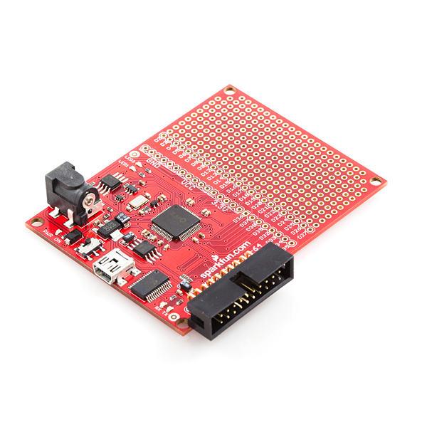
XMOS XS1-L1-64 Development Board
**Replacement: **DEV-10113. The new version eliminates the UART circuit. This page is for reference only.
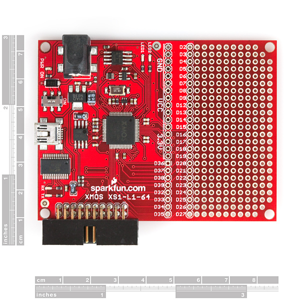
This is a development board for the impressively powerful XS1-L1, multi-threaded processor made by XMOS. The XMOS development board includes a XS1-L1-64 processor in a 64LQFP package.
L1-64 Features:
- Event driven processing at 400MIPS
- 64 kBytes of SRAM
- 8 threads
- 36 user I/O pins
- 8 kBytes of OTP memory for application boot code and security keys
A typical power consumption of 450µW/MHz
SparkFun's development board for this processor provides an FT232 to support a UART over USB, a XTAG header for either loading your code onto the external SPI flash or running your code as an XCore application. Thirty two user I/O pins are broken out for your prototyping needs. The board comes with the SPI flash already programmed with some simple example code.
The XS1-L1 is easy to use. The processor can be programmed using the XMOS Design Tools. A design tools supported USB to XTAG converter is needed to load your code onto the XS1. Our development platform can be programmed in the XMOS Development Environment. The SFE development platform can be programmed either by creating a project that uses the XC-5 Development Platform or by using the SFE.xn file found in the example code. Note that the XC-5.xn selects a 20MHz external oscillator. To have all timing I/O be properly scaled, you must change the oscillator frequency in the .xn file to 13MHz.
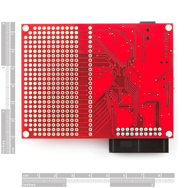
Note: There is a hardware bug on our current revision of this board. The bug springs from having the UART lines on the XS1 connected to both the FT232RL and the XSYS programming header. For now, to resolve this issue, we're cutting a couple traces on the board to take the XSYS RX and TX pins out of the loop (so don't be surprised if you see a couple of scratches on the bottom of your board). Specifically, we are cutting the traces connected to pins 19 and 17 of the XSYS header. With that fix the board no longer has the programming issue it did and programs completely fine. We do have a revised PCB incoming to correct this issue and will post the revision as soon as we run out of stock of the current version.
Community:
- Board: 2.5x3.3"
Comments
Looking for answers to technical questions?
We welcome your comments and suggestions below. However, if you are looking for solutions to technical questions please see our Technical Assistance page.
Customer Reviews
No reviews yet.


Hi!
I got this beautiful board some days ago but i cannot upload any code on it.
I got the Xmos JTAG2 programmer as well which is connected to the PC(Win XP sp3)
When i try to program the chip with the development tools recommended here, it shows me the following:
xrun: No available devices
Error: F03034 Failed to fully run flash inquisitor.
Drivers for Xtag2 installed.
I read in Xmos community forums that many people have
the same problem.
Any suggestions?
Thanks!
Turns out I needed to plug in the usb lol. xtag doesnt supply power to board I guess
Hi pinatapirate, thanks for your reply. I tried with xtag and usb cable (both connected) and at the beginning it didn't work neither i guess because i had ftdi drivers (to work with arduino). Now i try in other PC without ftdi drivers and it works. But i don't understand why needs power supply from the usb when in the first page of the hardware manual of the XJtag tells:
The XTAG-2 debug adapter can be used to
connect XMOS development kits to most PCs, and provide a 5V power supply.
THANKS!!!
I have the same problem
The SparkFun description of this board says "Our development board can be programmed in the XMOS Development Environment as if it were the XC-5 Development Board." This is true, but they don't mention that the XC-5 board uses a 20 MHz oscillator while their board uses a 13 MHz. This will throw off the timing of any code that uses clocks or timers unless you find the XC-5.xn file in the XMOS Design Tools' configs directory and change Oscillator="20MHz" to Oscillator="13MHz".
Does the FT232RL still connect to the XMOS chip? Is the new version the same functionally as the old with the rework?
The XTAG-2 programming/debug board is a general-purpose method for programming XMOS chips - irrespective of the kit they are in. This reduces the cost of new development boards (either XMOS or non-XMOS) and ensures that the (free) XMOS tools will support the programming of new kits without extra work.
The XC-1 board was designed before the XTAG-2 - and so includes on-board programming functionality through the USB port.
In future, it's likely that a single XTAG-2 board will interface to most/all XMOS-related development kits - irrespective of the board designer/manufacturer.
Can someone compare this board with the XC-1 board from XMOS? I like that the XC-1 has four cores and also that I can program it without having to buy a XTag2 debug adapter. What advantages does the Sparkfun board have? It isn't really cheaper since you have to pay $50 for the board and another $50 for the programmer. Is it mainly the SPI flash? What am I missing here?
Thanks!
David
I've made a comparison for the various Xmos/Sparkfun development boards. Check the link below:
http://zuzebox.wordpress.com/2009/11/13/xmos-development-board-comparison/
It looks like the inputs are 5 volt tolerant, but the outputs only drive up to 3.16V at 4mA or 8mA depending on the port.
I'm really excited to see this at SparkFun; I've got one of the XMOS XC-1 boards, and they're a pleasure to work with.
Two questions:
1. To clarify, am I right in thinking that the FTDI chip onboard only provides UART, and not a FIFO for doing code upload (necessitating the XTAG-2)?
2. Would it be possible to get a slightly more explicit listing of the ports supported on the 32 digital IO pins? In particular, the number of 1-bit, 4-bit, 8-bit, and 16-bit ports, and how they overlap. I feel like this might not be obvious to newcomers to the XMOS architecture.
I've got a list of the port pin outs on my blog:
http://zuzebox.wordpress.com/2009/11/11/port-details-for-the-sparkfun-xs1-l1-64-development-board/
The FTDI chip on the dev board can't be used to load code onto the chip or the SPI flash.
Nice to see XMOS has made it to SparkFun! It's an amazing chip that packs quite a punch!!
As Tony already mentioned, using just 2 threads (on a single core), it's possible to do VGA/NTSC (without additional hardware) and have a kick-ass video system.
When can we expect 16 core boards? :-)
-Yvo
Its great to see a new low cost board for the Xmos XS1 processor.
Check out the Xmos forum at:
http://www.xmoslinkers.org/
To see the power of the XS1 check out Yvo VDP VGA/NTSC video driver and his Super Mario demo at:
http://xcores.org/blog/2009/08/21/its-alive/
And my Manic Miner demo using the VDP software at:
http://zuzebox.wordpress.com/2009/11/03/manic-miner-on-x-one-console/
I'm hoping we can port these demos to Sparkfun's board in the near future
Is this programmable with the XTag2 debug adapter from XMOS https://www.xmos.com/products/development-kits/xtag-2-debug-adapter ?
Are SparkFun going to distribute the XTag2 programmer ?
Anyway: great move as always SparkFun: this will greatly help your camera range image processing!
It is and we are - it should be live really soon!
Yes, the board does indeed support the XTag2.
The board would support any USB to 20 pin JTAG converter except that the XMOS Design Tools only has drivers for a handful of serial to FIFO ICs. Any USB to JTAG converter using the FT2232 should be compatible. Check with XMOS's tech support to find out if a specific converter is compatible with their design tools.