×
SparkFun will be closed on Tuesday, December 24th, and Wednesday, December 25th, in observance of the Christmas holiday. Any orders qualifying for same day shipping placed after 2:00 p.m. (MST) on Monday, December 23rd, will be processed on Thursday, December 26th, when we return to regular business hours. Wishing you a safe and happy holiday from all of us at SparkFun!
Please note - we will not be available for Local Pick up orders from December 24th-December 27th. If you place an order for Local Pick-Up we will have those ready on Monday, December 30th.
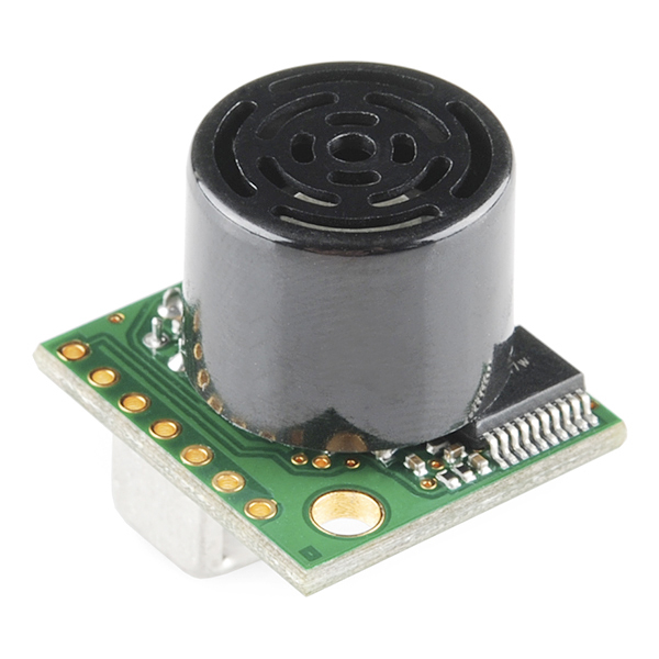
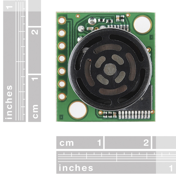
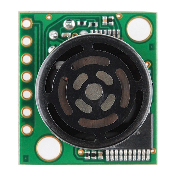
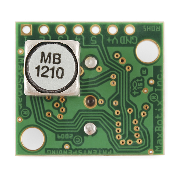
Ultrasonic Range Finder - XL-MaxSonar-EZ1
The XL series of MaxSonars are a super high-performance version of the easy-to-use sonar range finder from Maxbotix. The XL series of this sensor features higher resolution, longer range, higher power output and better calibration when compared to the LV version.
We are extremely pleased with the size, quality, and ease of use of this little range finder. The sensor provides very accurate readings from 0 to 765cm (0 to 25.1ft) with 1cm resolution. This sensor can be powered with anywhere between 3.3 and 5VDC.
Range information can be gathered through one of three methods - analog, serial, or PWM - all of which are active at the same time. The analog output will produce a voltage proportional to the measured distance, with a sensitivity of (Vcc/1024)V/cm. The serial interface is simple and formatted to RS-232, with voltages ranging from 0 to Vcc and terminal settings of 9600-8-N-1. Finally, the PWM pin outputs a pulse-width representation of the range with a scale factor of 58us/cm.
The Maxsonar-XL series is offered in the EZ0, EZ1, EZ2, EZ3, and EZ4 versions, each with progressively narrower beam angles allowing the sensor to match the application. Please see beam width explanation below.
- 3.3V to 5V supply with very low average current draw
- High acoustic power output
- All interfaces are active simultaneously:
- RS-232 serial
- 0 to Vcc output range
- 9600 baud, 8-N-1
- Analog, (Vcc/1024) / cm
- Pulse Width
- Real-time auto calibration and noise rejection for every ranging cycle
- Calibrated beam angle
- Object detection includes zero range objects
- Readings can occur up to every 100mS, (10-Hz rate)
- Free run operation can continually measure and output range information
- Triggered operation provides the range reading as desired
- Sensor operates at 42KHz
Ultrasonic Range Finder - XL-MaxSonar-EZ1 Product Help and Resources
"RS232" Output or Inverted TTL
If the ultrasonic range finder indicates that it has an "RS232 Serial Output" and is outputting an inverting signal with the voltage level based on Vcc, you could just use an inverting circuit using a transistor to invert the signal. This is not a standard RS232 that uses +/-12V. There are a few methods of flipping this signal through hardware or software. The resources and going further will provide specific examples.
Inverting Signal w/ Hardware
Doing a quick test using a retired NPN transistor from our storefront, I was able to get it working based on the circuit using a RedBoard Programmed with Arduino. I was using an Arduino so Vcc in my circuit was 5V. Since it's basically two diodes within the transistor, you will want to use resistors to limit the current. I just used two 330Ohm resistors just like I was turning on an LED. You probably do not need to do this but the values might need to be adjusted when using it at higher speeds or if the transistor is not fully turning ON/OFF. Testing with a multimeter, it worked as expected. An input of 5V would result in 0V (logic LOW) on the output since the transistor was turning on. With an input of 0V, the transistor would not be conducting so the output would be held HIGH at 5V. Using an Arduino serial passthrough for further testing, I was able to view the ultrasonic sensor's output data without any problems.
"RS232" Output and Inverting w/ Software
Otherwise, you could be clever in writing your code to store the value and possibly apply some sort of logical NOT operation. In Arduino, there is a special feature using software serial that inverts the signal by setting a parameter to true [ "Software Serial Constructor" – https://www.arduino.cc/en/Reference/SoftwareSerialConstructor ]. There was someone in the Arduino forums that provided example code to invert the output, parse the data, and output it through the serial monitor here => [ User "Goldthing" - http://forum.arduino.cc/index.php?topic=114808.msg864009#msg864009 ].
Connecting Ultrasonic Sensor to Raspberry Pi
There is a tutorial from MaxBotix that shows you how to connect ultrasonic sensors to Raspberry Pis => [ http://www.maxbotix.com/Raspberry-Pi-with-Ultrasonic-Sensors-144/ ]. Certain ultrasonic sensors listed in the article require an inverter. If the ultrasonic range finder's output serial output is " RS232 " like the sensors listed under "Ultrasonic Sensors that Require an Inverter" , this indicates that the signal is basically an inverted output with the voltage level based on Vcc.
Therefore, you would need to follow the tutorial and use a serial inverter in order to use it with the Raspberry Pi. If you are using a Raspberry Pi a transistor, Vcc should be 3.3V since the Pi uses a 3.3V system.
Resources and Going Further
Core Skill: Soldering
This skill defines how difficult the soldering is on a particular product. It might be a couple simple solder joints, or require special reflow tools.
Skill Level: Noob - Some basic soldering is required, but it is limited to a just a few pins, basic through-hole soldering, and couple (if any) polarized components. A basic soldering iron is all you should need.
See all skill levels
Core Skill: Programming
If a board needs code or communicates somehow, you're going to need to know how to program or interface with it. The programming skill is all about communication and code.
Skill Level: Rookie - You will need a better fundamental understand of what code is, and how it works. You will be using beginner-level software and development tools like Arduino. You will be dealing directly with code, but numerous examples and libraries are available. Sensors or shields will communicate with serial or TTL.
See all skill levels
Core Skill: Electrical Prototyping
If it requires power, you need to know how much, what all the pins do, and how to hook it up. You may need to reference datasheets, schematics, and know the ins and outs of electronics.
Skill Level: Competent - You will be required to reference a datasheet or schematic to know how to use a component. Your knowledge of a datasheet will only require basic features like power requirements, pinouts, or communications type. Also, you may need a power supply that?s greater than 12V or more than 1A worth of current.
See all skill levels
Comments
Looking for answers to technical questions?
We welcome your comments and suggestions below. However, if you are looking for solutions to technical questions please see our Technical Assistance page.
Customer Reviews
No reviews yet.


is there any way i can make the underwater depth calculation using this if not kindly suggest me one i have to use it in my ROV
Just a question, that perhaps someone can answer: Regarding the "beam width" and the "cone" in which the sensor senses within, it seems to be the case the the sensor will tell you the distance to the closest object within it's cone of vision.
Is this correct? In other words, it will only tell you the closest object it seem, but will not tell you where in the cone the object actually is. So it may know something is 40 inches away, but it has no idea if the object is directly in front, or to the left or to the right of the sensor. Is this correct? If so, this sensor seems ill-equipped to detect objects since there's no way to really know where the objects are that it sees. ??
It's true, it can't detect exactly where the largest object is in it's field of view, but that's a limitation of using ultrasonic sensors instead of others like IR/laser range finders with a much more limited detection zone. The workaround (and one of the best ways of taking advantage of the large cone) is to use two sensors instead of one, and use triangulation to determine where the largest object is in a plane. If you also need to, you could add a third in order to determine the exact position (+/- ~ 1cm) of the detected object in 3D.
"The sensor provides very accurate readings from 0 to 765cm (0 to 25.1ft) with 1cm resolution."
This might be misleading, from the datasheet:
"Objects from 0-cm to 20- cm range as 20-cm"
So it should be 20 to 765cm :(