×
SparkFun will be closed on Tuesday, December 24th, and Wednesday, December 25th, in observance of the Christmas holiday. Any orders qualifying for same day shipping placed after 2:00 p.m. (MST) on Monday, December 23rd, will be processed on Thursday, December 26th, when we return to regular business hours. Wishing you a safe and happy holiday from all of us at SparkFun!
Please note - we will not be available for Local Pick up orders from December 24th-December 27th. If you place an order for Local Pick-Up we will have those ready on Monday, December 30th.
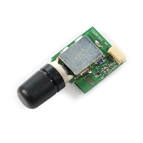
50 Channel D2523T Helical GPS Receiver
Replacement: None. Unfortunately the supplier for these helical GPS Receiver is no longer in business so we can no longer carry them in our catalog. This page is for reference only.
The D2523T is a compact GPS smart-antenna engine board, which comes equipped with a Sarantel GeoHelix high-gain active antenna and GPS receiver circuits. The module is based around the high performance 50-channel u-blox 5 platform.
The omni-directional antenna provides great sensitivity, even when you don't have a clear view of the sky. Whether this receiver is in your pocket or under your car seat, you are likely to pickup a rock solid GPS signal.
The module operates at 3.3VDC and outputs standard format NMEA strings over the TTL/UART pins. It has up to a 4Hz update rate.
Not sure which GPS module is right for you? Check out our GPS buying guide!
Note: As of 2/6/2012, we are now shipping units that are based on the u-blox6 GPS engine. Both datasheets are listed below for your reference.
- 50-channel u-blox engine
- Omni-directional Sarantel active antenna @ typical gain: +26dBic
- 1 Hz position update rate
- <1 second time-to-first-fix for hot and aided starts
- 160dBm SuperSense® acquisition and tracking sensitivity
- Accelerated startup at weak signals for modules with KickStart feature
- Supports AssistNow Online and AssistNow Offline A-GPS services; OMA SUPL compliant
- High immunity to jamming
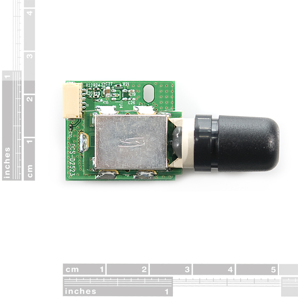
- PCB main board size 25 x 23 mm
- UART (TTL) interface
- 3.3V supply voltage for low power consumption
- [Datasheet](http://www.sparkfun.com/datasheets/GPS/Modules/D2523T V1.pdf) (2523T)
- Datasheet (2523T-6)
- u-blox 5 Protocol Specification
- u-blox 6 Protocol Specification
- u-blox Configuration Software
50 Channel D2523T Helical GPS Receiver Product Help and Resources
Core Skill: Programming
If a board needs code or communicates somehow, you're going to need to know how to program or interface with it. The programming skill is all about communication and code.
Skill Level: Rookie - You will need a better fundamental understand of what code is, and how it works. You will be using beginner-level software and development tools like Arduino. You will be dealing directly with code, but numerous examples and libraries are available. Sensors or shields will communicate with serial or TTL.
See all skill levels
Core Skill: Electrical Prototyping
If it requires power, you need to know how much, what all the pins do, and how to hook it up. You may need to reference datasheets, schematics, and know the ins and outs of electronics.
Skill Level: Competent - You will be required to reference a datasheet or schematic to know how to use a component. Your knowledge of a datasheet will only require basic features like power requirements, pinouts, or communications type. Also, you may need a power supply that?s greater than 12V or more than 1A worth of current.
See all skill levels
Comments
Looking for answers to technical questions?
We welcome your comments and suggestions below. However, if you are looking for solutions to technical questions please see our Technical Assistance page.
Customer Reviews
No reviews yet.


Before I fry my D2523T, I wonder if any of you curious hackers out there have checked the board for a 1 sec GPS timing signal? Is the 1 PPS available on any of the pins or traces on the board?
Which chipset is it exactly? There are an half dozen of UBX-G6010 versions.
UBX-G6010-ST UBX-G6010-ST-TM UBX-G6010-SA UBX-G6010-NT UBX-G6010-Sx-DR ...
Another request for the full part number and/or chipset. I'd like access to raw data (ephemeris). That's the 'T' and 'P' variants.
The description was updated "see Note 2/6/2012" so I guess the LEA6-T version is included which allows to access the raw data. If that is not the case please respond or update the description accordingly!
Very cool! Looks just like the GS407 except with an easy to use connector and $10 cheaper. Good stuff!
Can someone point their differences? It seems they are the same!
Does anyone happen to know if this GPS engine has the I2C interface, and if so what pins it's on? I'd like to use I2C instead of serial and don't mind soldering to the module. Thanks!
I just got this module. About ready to hook it up and the antenna shield came off. I noticed in older version of this product that you photographed it this way. I was just wondering. Should it slide off? Should I glue it on? Not clear if this is designed this way.
Thanks for any suggestions or information.
Cheers!
Edit: grammar/punctuation/spelling
Yes, the radome should come off. It is designed so that the radome can be permanently mounted (e.g. sticking out of an enclosure) and still allow the GPS module to be removed from the inside.
I have read through all the data sheets. There are many places where it says you need to connect a backup battery but it never says what voltage. Can someone answer this simple question please?
I think it's safe to assume you use the same as the supply voltage....
I can neither update firmware, or save configuration where it will not be lost on reset. Is this possible with his device or not.
I understand that the board is powered with 3.3v. Should I use a Logic Level Converter for the Tx/Rx Lines as well? Does anyone have a wiring diagram for this gps and the arduino duemilanove or mega?
I finally got everything working. I used a logic level converter with 3.3v for the serial lines, I had to cut a em406 cable and check the datasheet pins as the em406 breakout board is incorrect for this gps. I used the serialsoftware example sketch for the arduino program and waited a few minutes for a fix. I downloaded the u-blox v7 software and was very impressed! I am now trying to update the firmware but don't know exactly what to do. Anyone know how to update the firmware on this guy?
is it possible to turn off all messages and poll the unit for specific messages?
is this u-blox GPS can be used with IMU for UAV's state estimation?! any help would be great
can this u blox GPS be used with IMU for UAV state motion determination? any help would be great?
I would be appreciate for any information about the LED connector (pin #6) on this module. For now, its constantly OFF (TTL 0). And there is no explanation for its behaviour in documents.
This mystery is solved: LED is flashing when GPS module is acquired necessary information (GP RMC , for example) form the SVs. Its flashing every time as module throwing information to the UART.
Ex.: $GPRMC,012817.00,A,6059.34472,N,07312.41211,W,0.195,,200612,,,A*65
What is the most common cause of failure on these units?
What precision does this module have?
I'm among those bad-luckers, mine 406 can't get fix - can only track 3 satellites most and sync. time. Tried various clear-sky locations in different regions. Seen rumors some got lucky after switching from USB FTDI to battery-based PSU - unfortunately that didn't work for me neither. Also been reading there was a broken set of devices with faulty antenna soldering. Anyone with a similar experience?
I bought one a few months back -- worked great the first couple of days. Now, no matter how many satellites signals it distinguishes (u-blox 6.01 software driving) it simply will not get a fix -- or a time. I've seen zero satellites for hours in a clear sky then 16 all of a sudden at the same location (Durham, NC). It isn't obvious to me there is an assembly issue with the one I have.
I read u-blox's GPS compendium and decided to upload an almanac (not that that explains the inability to decode the time from the many satellites it sometimes syncs with), but that fails with this unit and the u-blox 6.01 software. The flash update fails due to a timeout. Interestingly the URL for the 5day (chosen at random) almanac returned a file which has a UBX command embedded at the beginning. I wonder if this confuses the unit because u-blox s/w issues its own UBX command before stuffing in the almanac payload.. (just a guess... I'm no expert) URL: http://alp.u-blox.com/current_5d.alp
that's about 3 issues all in one... any suggestions?
I make personal trackers, this is the best GPS receiver/antenna combination I have used yet. It's well worth the money. Whether it is the chipset that is ideal or the antenna's radiation pattern which is ideal (it is) , I am not sure but the combination works. I put alot of it down to the good antenna.
I just received this module and it appears the little green plate on the top of the antenna has come loose.
The contacts look tiny. Is there any way I can fix this or should I send it back?
I connected this module with the EM-406 BOB but I get no connection to it. If I look at the pinout discribed in the datasheet it does not match the pinout of the breakout board. Any hints?
De soldered the cable and connected it without the BOB and now it works. So don't get the EM-406 BOB if you want to use it with this module ;-)
So if I have understood it well, the pin in the right go to pin Tx in arduino, pin2 (second in the right) to pin Rx in arduino, next to GND in arduino and the fourth to the 3v3 in arduino. The two pins in the left can be unpluged. Is that right? Thanks
This comment was salutary Enrique. Thanks for spotting it.
I'm curious the datasheet mentions a Galileo upgrade, what does one need to do to get this?
i was wondering,
i am using a 5V microcontroller,
are ports on the GPS-09566 have 5V tolerance, as i will be sending signals from my micro controller back to the GPS.
regards
Great Product... Works Great!!
anyone got it working with arduino Duemilanova ?
Somebody knows if this GPS works well with Arduino using the TinyGPS library? any advices?
Great unit however the UBX-G5010 chip dosent allow firmware updates or saving configuration changes. If you change baud rate then power off, defaults to 9600 baud on next power up.
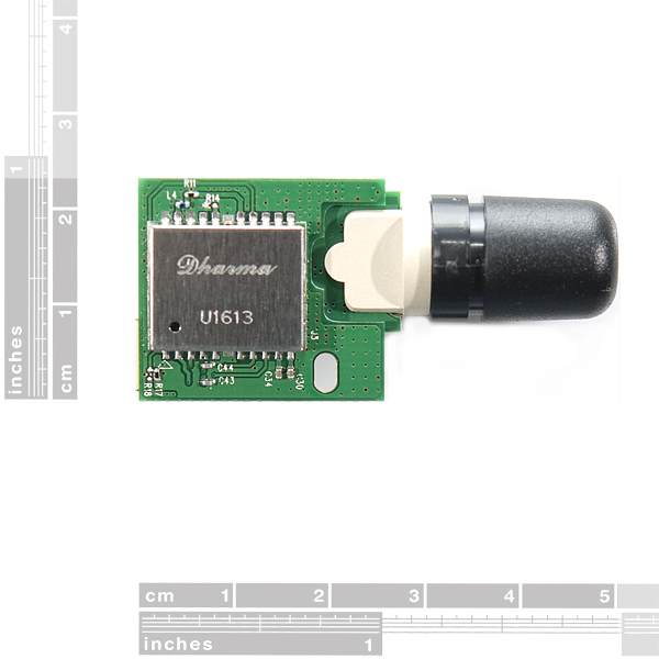
The picture shows a Dharma U1613 chip. Is this some kind of a uBlox clone?
9600 8/N/1 works for me.
Maybe I'm blind but at what bit rate do you interface to this at?
The datasheet (page 3) indicates 5V supply. Everything else indicates 3.3V. Be careful!
Tairc:<br />
<br />
So does this one have the "enhanced" firmware that allows for RAW measurement output?
Same question 3 years later. Still no answer?
Will this work with the ardupilot?
yes but you have to boot loaded its easy
I'm sorry, but I don't understand very well... Loaded? with what? how? Do you know if this GPS works well with Duemilanova and TinyGPS library?. Thanx