Gyro Breakout Board - LPR530AL Dual 300°/s
Replacement: None. The LPR530AL IC is end-of-life and so it's time for this breakout to step aside and make way for more cool stuff in the catalog. This page is for reference only.
This version of the breakout removes the issue with the high-pass filter. We removed R5 and R8 and replaced C1 and C2 with a jumper.
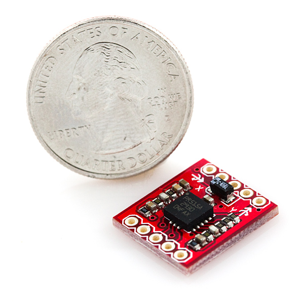
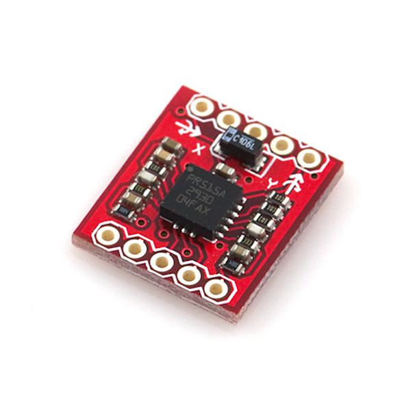
This is a breakout board for the ST's dual-axis LPR530AL gyro. The LPR530AL measures angular velocity along the pitch and roll axes with a full scale of ±300°/s. Two different analog outputs are provided for both the x- and y- axes - one 1x amplified and the other 4x amplified.
A regulated voltage between 2.7 and 3.6VDC should be supplied to the power pins. You'll just need to connect the outputs to an ADC, and you're ready to go.
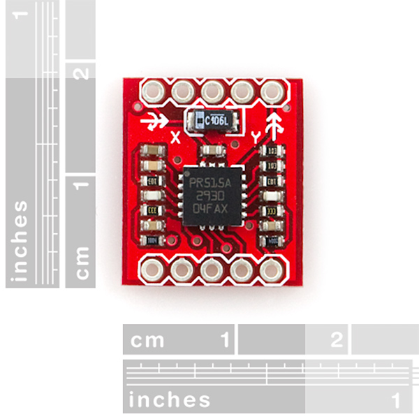
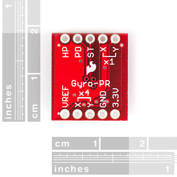
This breakout board includes the gyro and all necessary filtering capacitors as shown. The 1x and 4x amplified outputs of both axes are connected to the 0.1" pitch headers, along with the power-down, self-test, high-pass filter reset, and power pins.
Note: The picture is inaccurate and does not reflect the new changes. When we get the new version in stock, we will get a new picture. You can refer to the schematic and Eagle files below though.
Replaces:SEN-09413
- 2.7 to 3.6VDC power supply
- Dual axis, pitch and roll sensing
- 1x and 4x amplified outputs for each axis
- Low power consumption
- All necessary filtering components included
- Access to power-down, self-test, and high-pass filter reset pins
- 0.6x0.7"
Comments
Looking for answers to technical questions?
We welcome your comments and suggestions below. However, if you are looking for solutions to technical questions please see our Technical Assistance page.
Customer Reviews
No reviews yet.


.
Hey guys,
I couldn't find any code for this chip so I've decided to share the code that I wrote. It seems to be working fine with me, but feel free to comment. I'll also upload a picture of the connections.
Connections: http://imageshack.us/photo/my-images/707/connectionsg.jpg/
Code: http://www.text-upload.com/read.php?t=5073
does anyone have a good arduino code for this gyro? I've looked everywhere I couldn't find anything.
So as I understand, the Vref voltage is the zero rate voltage which you can compare the X and Y outputs against. Does anyone have any experience in whether this actually helps the accuracy or reduces it because of the doubled ADC noise? (You have to convert both the X/Y and the Vref to digital, so when you subtract them, the noise is doubled) On the other hand I suppose that if the 3.3V supply is unstable, using Vref reduces the X/Y instability. So, using the 3.3V output from an Arduino 2009, and the AVR's ADC, is the Vref any useful really?
Also has anyone tried to measure the noise of the 4x outputs compared to the 1x outputs? I would assume 4x would give you better accuracy, but does it really?
hello all..
Iam using LPY5150AL Breakout gyro. I have connected to a PIC16F877A microcontroller.The problem is that iam getting outputs of gyro around 1100 -1300 deg/sec when i rotate the axes.I donot know whether these values are correct are not??can anyone help me out..!
The formula used is:
X_deg=((V_out-V_reference)*5000/1024)/(sensitivity)
where v_ref=1.23 as suggested in datasheet.
THANKS ALOT..!
Does anyone know what to do with the Vref pin? The only thing the data sheet says is that its a "reference voltage", which isn't very helpful. Does that make it an input I need to give it or an output that I can use if I so choose?
hey in the datasheet the pin diagram tells that its an output pin.Its used to test the gyro.
I ordered the previous version, and it arrived early this week. How do I check which version I have?
We will get stock on there very soon. You can place a backorder for now and we will ship them when they're ready!