Ganged Programming with AVR ISP MKIIs
SparkFun Production's ganged programmer.
Only a few years ago, it seemed crazy that we needed to make 100 of any product. Now, it's very common to see builds of 1000 or more! We knew the day would come when our one-at-a-time programmers would need to be upgraded. In November of 2010, I was researching how to program and test multiple boards at the same time (aka ganged programming). After receiving some expensive quotes from companies that make ganged programmers (one was actually over $11,000!), I quickly started thinking about making a DIY ganged programmer. No need to spend 11K...how hard can it be?
Well, throughout my prototyping, I found that there were two rather difficult challenges: (1) getting multiple programmers to talk at the same time and (2) the hardware. I have become very close to batch files and MS DOS commands in the past three years (because we use them all the time in SparkFun Production). So the first challenge was achievable without too much pain. I just had to dive a little deeper into the MS DOS command set and try out a few combinations of commands. The second challenge proved to be much more difficult. Designing an apparatus (cheaply) to apply pressure evenly on 200+ pogopins has proven to be very difficult task. Although the current method (as described in this tutorial) is working in production, we are still trying to think of ideas to improve it.
Overview of the sections:
(I) Working with Tricky Batch Files
Before I even thought about the hardware for this project, I knew that I needed to get multiple programmers talking at the same time. This section is dedicated to working with batch files and how that can enable you to use multiple AVR ISP MKIIs to gang program multiple Atmel chips. To start, you can download some example batch files here:
If you know a ton about DOS commands and/or have a strong background in writing code, then this section may be a bit of review. You may be able to just download the batch files from the link above, take a look at them and tweak them to your liking. For those of you that are new to batch files and/or code, I will show you how to alter these batch files and customize them to your needs. You can simply change some directory locations and hex file names, and you will be ganged programming in no time.
(II) Designing Large Pogobeds
After I finally had the "blinking LED" moment and actually got two programmers to program at the exact same time, I was ready to move on to the challenge of creating some hardware that could talk to multiple boards. Luckily, I had already started making some testing jigs that could test multiple boards. We call them panel testing jigs here in SparkFun production. This section will cover how to design a massive pogobed. I will share some tricks I've learned along the way to speed up the process and help avoid mistakes. If you haven't already, I recommend checking out my previous tutorial on pogobeds. Jumping right into designing, ordering and building a very large panel-sized pogobed can lead to some expensive mistakes, so I would also recommend that you try making a smaller single-board pogobed first, and then move onto the larger style. But heck, if you're feeling ambitious, maybe just reading the previous tutorial should suffice! If you'd like to jump right in, you can download the eagle files for the Arduino Pro Mini Ganged Programmer/Tester here:
Here's some pictures of a completed programmer taken directly from SparkFun Production:
 |
 |
 |
 |
 |
 |
 |
 |
Section I: Working with Tricky Batch Files
Over the past couple years, I had been working a lot with batch files. Like I said before, we use them every day in production. Up until now, we had always been using them one-at-a-time (i.e. we would just use one single batch file to program one single board). When the batch file completes, we switch out the board and run it again. I knew that if I could call multiple MKIIs from the same batch file at the same time, then I'd be really close to ganged programming. For my final product, I knew there were four problems I'd need to solve:
- Each programmer needs to start at the exact same time.
- Each programmer needs to be addressed individually.
- Each instance of programming needs to report back the results.
- Each set of results would need to be parsed and simply say "success" or "fail".
Problem, #1
It turns out that you need two MS DOS commands (used in sequence) in order to start multiple batch files at the same time. They are the "CALL" function and the "START" function. CALL enables you to call one batch files from within another. That's easy enough. Why not just have one "master" batch file call a bunch more? This would work, but the problem with CALL is that it actually imports the other batch file into the same original command prompt window. This means that if you were to CALL multiple outside batch files, they would be called in sequence. I really wanted them to be called at the exact same time.
And so I continued to try other MS doss commands, and came across the START command.
HINT: if you ever want to know all the commands available in MS DOS, a good place to start is opening a command window and typing "help" and enter. But also know that there is much to learn about each of these commands. Google searches can help you with this. There are many forum threads and blogs about how to harness the power of batch files. For example, the FOR and FC (file compare) commands are very useful. These two in particular ended up giving me the capability to parse the programming results.
START enables you to start a new window with a new set of commands running. The beauty of START is that it doesn't stop the original batch file. Using them together, I can start multiple batch files at the exact same time.
EXAMPLE1:
start call "batch_file-1.bat"
start call "batch_file-2.bat"
The above example will start both "batch_file-1.bat" and "batch_file-2.bat" at the same time. Although the batch file will run the commands from top to bottom, the START command does not wait for the first batch file to complete. It starts it in a new window, and then moves on immediately. Although they are being started in sequence, it is virtually instant.
Let's look at the master batch file, called "GANG.bat".
HINT: In order to look at and edit a batch file, you must right click on it and select "edit". This will open the batch file in notepad -double clicking on the batch file will actually run the batch file.
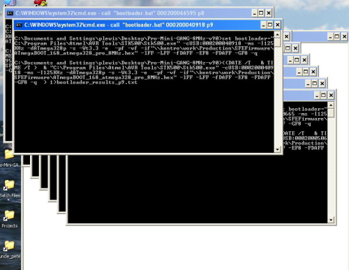
In the GANG.bat file you will see that for each step of programming, there are 9 "START CALL" lines for each programmer to be called. For now, don't worry about the p1s, p2s etc. (they will be explained later) Check out how in the master batch file, in the section for the bootloader, you can see all 9 "START CALL"s:
:XXXXXXXXXXXXXXXXXXXXXXXXXXXXXXXXXXXXXXXXXXXXXXXXXXXXXXX
:bootloader
start call "bootloader.bat" %p1% p1
start call "bootloader.bat" %p2% p2
start call "bootloader.bat" %p3% p3
start call "bootloader.bat" %p4% p4
start call "bootloader.bat" %p5% p5
start call "bootloader.bat" %p6% p6
start call "bootloader.bat" %p7% p7
start call "bootloader.bat" %p8% p8
start call "bootloader.bat" %p9% p9
goto MENU
:XXXXXXXXXXXXXXXXXXXXXXXXXXXXXXXXXXXXXXXXXXXXXXXXXXXXXXX
When you run this part of the master Batch file (by selecting step 3 from the main menu), 9 new windows pop up instantly and begin running at the same time. It's impossible to watch all of the data readout, so that is why we will parse the data later.
Problem #2:
Okay, so the START CALL combo solves problem #1, but what about calling each programmer individually? It turns out that when using STK500.exe (the program used to control the AVR MKII programmer), you can actually specify the serial number of the programmer you'd like to control. Up until now, we have always just used one programmer per computer. This is important because all of our previous batch files would use something like this to control the MKII:
C:\Program Files\Atmel\AVR Tools\STK500\Stk500.exe -cUSB -ms -I125KHz -dATmega328p -s -wt -e -pf -vf -if"ATmegaBOOT_168_atmega328_pro_8MHz.hex"
The line of commands above runs Stk500.exe with ten "settings" (aka "flags"). The flag that I was concerned with was the "-cUSB" flag. If you have any single programmer plugged into your computer and run this command, it will automatically connect to that programmer and run the command. BUT if you specify a serial number like this "-cUSB:000200029267", then you can command Stk500 to only talk to that specific programmer. Problem #2 solved.
HINT: If you ever want to know more about a specific flag, you can type the following into your command prompt window. You should get the entire help readout. *Note, you will have to install AVR Studio 4.
C:\Program Files\Atmel\AVR Tools\STK500\Stk500.exe -h
The line that I was concerned with was the "-c" flag. This is what reads next to that flag:
c Select communication port; 'COM1' to 'COM8' for STK500 or AVRISP, 'USB'
or 'USB:sernum" for AVRISP mkII. If this parameter is ommitted the
program will scan the COM ports for STK500/AVRISP only.
Problem #3:
Another trick I learned along the way is that you can send variables when you send a command. **Thanks Brad in IT!!** This makes calling a batch file much like calling a function within your main loop of a program. When you want to access those variables within the "called" batch file, you simply use type a %1 or %2, for either the first or second variable (note you can have as many as you'd like actually). One variable that I would like to send a batch file is the specific serial number of a programmer.
Let's look again at the first START CALL of the "bootloader" section of the master batch file:
:XXXXXXXXXXXXXXXXXXXXXXXXXXXXXXXXXXXXXXXXXXXXXXXXXXXXXXX
:bootloader
start call "bootloader.bat" %p1% p1
The "%p1% p1" are two variables that I am sending to the batch file "bootloader.bat". This command will send these to variables to the batch file, and within that batch file you can use them by typing a %1 or %2 for either the first or second variable, respectively. The first variable "%p1%" is not going to send the characters "p1". It is actually going to send a defined variable from earlier in the master batch file. This variable is actually defined, (aka "set" in MS DOS command land) in the batch file "MKII-DEFINES.bat". If you look at that batch file, you can see where the p1 is being defined as an actual serial number:
:send this batch file two variables
:variable one is the programmer variable (p1, p2, etc.)
:variable two is the letter of the programmer (a, b, etc.)
:the if statements (below) link the two variables
:example
:call MKII-DEFINES.bat p1 a
:This will set the variable "p1" to 0000B0034766
:we use this in SFE production to make it easier to setup
:we can now just send a letter, rather than the entire serial number
:we slap stickers on our programmers (a-v) so we don't have to deal with the long serial number.
set a=0000B0034766
set b=000200040799
set c=000200040603
...
if %2 == a set %1=%a%
if %2 == b set %1=%b%
if %2 == c set %1=%c%
...
**Note, if you are going to use this batch file, you will need to change these serial numbers so that you can call your specific MKII programmers.
After the MKII-DEFINES.bat has been called, just like in a make file (or an arduino sketch for example), from this point on, I can use these variables (p1, p2, etc.) and it will plug in the serial number for that variable. Instead of actually sending a "p1" to the called batch file, it will now send "000200029267". For it to work in a batch file, you must surround your variable with percentage signs like so: "%p1%".
So this ability to send variables to called batch files allowed me to start unique batch files that each are talking to unique programmers. Problem #3 solved.
Problem #4:
The second variable, which is simply "p1" (without the percent sign around it), WILL actually send the characters "p1". This is useful in the bootloader batch file, because I can use it to create a unique file name and save the data read out to a text file.
The key to solving problem #4 was as simple as one single ">" character. Yet another trick I learned from Brad in IT was the ability to send data readout to a text file. All you have to do is put a ">" in front of your command. This turned out to be very useful for saving the data readout and checking that the programming went well. One other thing to note is that after the ">" you must give a file name, and then the command.
> file_name.txt echo hello
The above example would create a new text file named "file_name.txt" (or write over an existing one), and send the text "hello".
Now let's take a look at the actual bootloader.bat file. This is the entire batch file:
set bootloader="C:\Program Files\Atmel\AVR Tools\STK500\Stk500.exe" -cUSB:%1 -ms -I125KHz -dATmega328p -s -wt -e -pf -vf -if"ATmegaBOOT_168_atmega328_pro_8MHz.hex" -lFF -LFF -fDAFF -EF8 -FDAFF -GF8 -q
> bootloader_results_%2.txt ((DATE /T & TIME /T) & %bootloader%)
exit
Notice the %1 and %2 in these command lines. Right after the "-cUSB:" flag I put the %1 variable. This is going to pass the variable "p1" which is actually the serial number of that programmer ("000200029267") and it will ensure that I connect to the programmer I want. The second variable, "%2", is going to actually plug in the characters "p1" and create a text file named, "bootloader_results_p1.txt". This is useful because I can now have this data saved to a unique text file with a unique file name. Plus, I can parse it later to ensure the programming was successful.
In order to parse the data, I needed something that could understand the readout and decide if it's good. I did a little surfing, and found a Windows XP command line function called "FC" or File Compare. I did a little more surfing and found a command called "FINDSTR" or Find String. These two commands allowed me to create the batch file called, "Check_results.bat" This is how it reads:
> results_%1_less.txt ((FINDSTR /C:"Signature is 0x1E 0x95 0x0F" bootloader_results_%1.txt) & (FINDSTR /C:"FLASH verified successfully" bootloader_results_%1.txt) & (FINDSTR /C:"Fuse bits verified successfully" bootloader_results_%1.txt) & (FINDSTR /C:"Lock bits verified successfully" lockbits_results_%1.txt) & (FINDSTR /C:"FLASH verified successfully" testcode_results_%1.txt))
set step1=FC results_%1_less.txt results_good_example.txt
FOR /F "tokens=*" %%i IN ('"%step1%"') DO (if "%%i" == "FC: no differences encountered" echo Success) & (if "%%i" == "*****" ((FINDSTR "Signature VTARGET Could" bootloader_results_%1.txt) & COLOR 0c))
The FINDSTR searches for specific strings within the "bootloader_results_p1.txt" file. Note, it could be "bootloader_results_p2.txt" depending on which variable I send it from the master batch. The "/C" is a setting for the FINDSTR command that ensures it will only look for the exact string matches. If it finds any of the specified strings, then it will send those to a new text filed called "results_p1_less.txt". By using FINDSTR and ">" in this way, we can create a "cleaned up" version of the data readout. It will only have the lines that we are concerned with.
The second command simply defines "step1" as the command set we'd like to reuse in the following FOR command. Now whenever we want to call the commands in "step1", we can simply write "%step1%".
The FOR command in the third line compares each token (aka line of data) found in results_p1_less.txt to a second text file called, "results_good_example.txt". If it ever finds "FC: no differences encountered" then it echo's "Success". If results_%1less.txt is missing any key ingredient, then it will always have the alert line, "*****", indicating something is wrong. It will then search the original data readout for any errors that we care about. I also added the color change to 0c (RED), to help indicate failure.
And there you have it, all four problems solved. Now...onto hardware!
Section II: Designing Large Pogobeds
Making a very large pogobed isn't much different than making a smaller one. The main difference is that you are going to be dealing with many more connections, and so the hardware becomes a little more complex. By increasing the amount of pogopins (and spreading them out over a larger area) the pressure on your test board becomes much more important. With a single board, you can simply hold the board in place using your fingers or use some "nubbins" that turn and lock the board into place like seen in these pictures:
With a much larger pogobed, like the Arduino Pro Mini Ganged Programmer, you are going to need something that can push down on the test board (really it's a panel of boards). We need to ensure there will be equal pressure across the entire panel. This is why I designed a plexi-glass "waffle press". Check it out:
 |
 |
 |
 |
 |
 |
 |
 |
To get started, it would recommend downloading the eagle files for this pogobed and taking a look at each layer in Eagle. You can download the eagle files here:
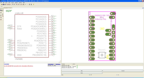
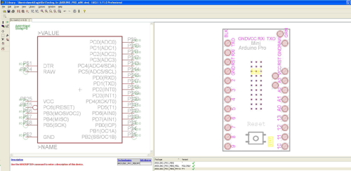
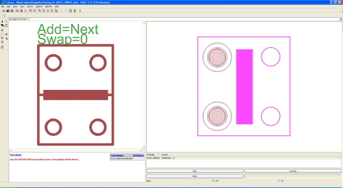
In addition to looking at the board layout, pay close attention to the schematics. I created two important packages that greatly speed up the design process. First, I created a new device called "Arduino Pro Mini". This device is it's own thing within eagle, it doesn't actually have any of the components of the Arduino Pro Mini, but it does have the pin-outs (aka thru-hole pads) that I want to test. By creating a custom device dedicated to the Arduino Pro Mini, I can get my spacing of pogopins correct once (while creating the package), and then later duplicate this device in the bottom layer PCB schematic/board. I won't have to place 200+ pogopins! Instead, I will have to place 8 boards (or better known by eagle as 8 devices).
The next trick I'd like to share is the fact that I created a separate variant of the Arduino Pro Mini Device that will be dedicated to the middle layer of the pogobed. For this package variant, I only want drill hits (so that the pogopins can pop through the middle layer PCB). But the problem is, eagle won't let me link a package that has only drill hits to a symbol that has multiple pins. Eagle always needs to link pins to pads when creating a variant. So, my solution was to add SMD pads to the bottom of the package. I can link any pins to any pads, cause when using this variant, I am not concerned with any nets or traces. My middle layer is not going to have any nets or traces. It's only going to include drill hits for the pogopins to pop though. Another nice thing to add to the middle layer package is some tplace layer (aka white ink) to show the dimensions of each board in the panel. Once I had this variant created, I simply needed to change the package within the original pogobed bottom PCB to the new "pogobed middle layer" package. It keeps the dimensions for me and I don't have to carefully place 200+ drill hits.
I would also like to mention that I created a part within my eagle library for the hinges. This helps a ton when it comes to laying out the spacing for the plexiglass "waffle press". Also, throughout my experimenting with wacky ideas, I have learned to let the fab house do the precise drilling. You can always break out the drill press and go for it manually, but a PCB fabrication house is always going to get the drill hits exactly where you want them. So creating the Hinge (and adding the exact drill holes I need for mounting) makes assembling this massive pogobed a lot easier.
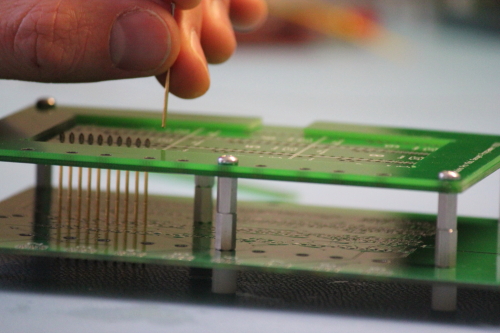
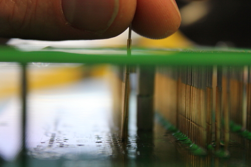
When assembling, I would recommend first putting the top, middle and bottom PCBs together with the hex metal standoffs, nylon standoffs and 4-40 screws. When you place this on a flat surface, it holds the layers at the perfect height so that you can easily drop each pogopin into place like so:
Also notice how I am placing an inner row of pogopins. In order to access each solder joint, you have to assemble it "row-by-row" and start with the inner rows.
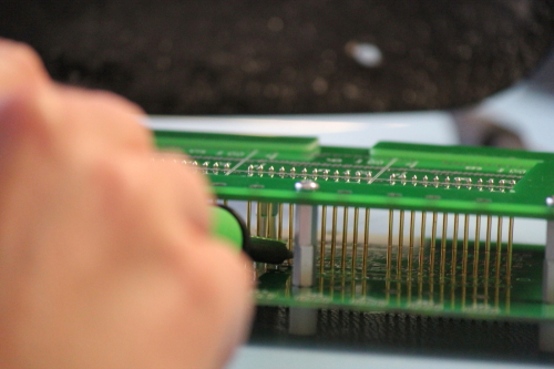
Notice how you'll have to reach in there with your iron. It's a bit of a pain to see what you're working on, but if you set your chair lower (or have a high work bench) that can help avoid tweaking your neck to badly. When I build one of these larger style pogobeds, I always do it row-by-row, and by that I mean (1) drop in all the pins for the inner most row, (2) solder that row into place, and (3) start and the next row.
In this picture I wanted to show the fillets on the right side. Notice how the long shaped pads have plenty of pad space to allow for a nice and large fillet of solder. This helps keep the pogopin in place and give it extra structural strength.
When it comes to assembling the "waffle press" I recommend using 3/4" clear plexiglass.
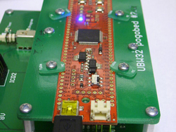
Any thinner and it will bend too much. It is also nice to use clear (rather than a colored or black plexi) because then you can see through to the boards. It is especially important for this product (the Arduino Pro Mini) because we need to see the STAT LED. The STAT LED is going to be our indication that the board is working properly.
The rubber strips can be any kind of rubber, but it would be good to ensure that it is tough enough that it can push down on the panel of boards without too much compression.
It also needs to be as thick (or thicker) than your tallest component.
See how in the picture above the rubber hits the panel of boards, but the plexiglass actually sits above the components of each board. We actually use left over scrap rubber from our production soldering iron kits. To glue them in place, we use gorilla glue. As with any gluing project, I'd recommend being very careful not to get any of it on your pogopins and/or boards under test. I used as little as possible and was very careful to place small drops exactly where I needed it.
Once you've got all the pogopins soldered into place and the hinge fully assembled, the last thing to do is get some clamps of your choice.
You can definitely hold the waffle press down without clamps, but it makes life much easier when developing the programming batch files and test code. I have included a slightly modified version of our production batch files and test code in the download above. If you have any questions, please feel free to comment below. We are always looking to improve our processes, so any suggestions are also welcome! Thanks for reading and happy DIY ganged programming!




a few ideas i can think of to improve it
1: add a push button that the plexiglass hits, to act as a 'lid switch'
2: use a microcontroler for the programing, and monitoring the lid switch
with the microcontroller watching the lid switch, it can inform the desktop when the lid is closed, and automaticaly begin programing
since you are SPI flashing all the chips with the same image, you can cheat, and share the master out between every target, you just need to monitor the master in's and detect if any of them have an error, and have some retry procedure for the last command
Nice, I like the idea of the testbed talking back to the batch file. This is something that we could use a lot on other designs too. I have never been able to have a batch file listen to a specific com port. Do you know of any MS DOS commands that will listen to a com port?
About your second idea for busing the MOSI line to each board, it sounds like a good idea, but we really need to hear back from each board individually. I guess this could be done with some sort of MUX on the MISO lines, but then we'd be listening in sequence, rather than all at once. But hey, if there is a way to use mux and one programmer, this may be a much cheaper way to do it, even if it's a bit slower.
Thanks for the ideas!
If it ever came time to rewrite the gang programming script, I'd strongly suggest picking up Python to do it. Python is really well-suited for these kinds of scripting and automation tasks, and it makes cake out of things like multithreading, handling COM ports, parsing logs, and just about anything else you could ever want.
I like the idea of the lid switch, but I'd take a slightly different approach. Make a box with an arcade button and one of the red/green LED matrixes. Every time you slap the button, it sends a message to begin programming. When programming is done, the status gets sent back and displayed on the LEDs (green pass, red fail). That way the operator can just focus completely on the programmer and never have to look back and forth between the programmer and the computer.
you could even go one step further if you have a linux computer handy
use udev to detect when your custom programer is plugged in, and then auto-run the programing script
then you dont even need the computer to use it, just plug it into a usb extension that disapears under the table and it 'magicaly' works
Why cant you build something in C DOS program that does your listening and have it return an 1 or 0 to your batchfile? I thought in the DOS 5.0 days you could do this.
While you might need to cop out and use a (very) short C/Python/whatever program to read from the serial port, if you can get away with a single integer value, then just reading the return value would do, and you could keep all of your logic in the batch file.
If you're programming a thousand at a time, though, then cutting out the interaction with the computer might well be worthwhile.
If you want something cheap and nasty and without any non-batch software on the host, then get a keyboard controller and connect the lidswitch where the enter key goes via an edge detector. Then you can just PAUSE at the end of each programming cycle, and it will magically continue each time you close the lid. It seems one can get such an IC in DIP fairly cheaply, so this needn't involve cannibalising a keyboard, either:
http://au.element14.com/holtek/ht82k629a-40diplf/ic-usb-ps2-cont-win-2000-keyboard/dp/1420877
While doing this all in C++, Python, PERL, etc. is probaly more "proper" and "efficient", if you are comfortable using batch files and they do what you want, then use them. :) As far as looking for input from the outside into the batch file (looking at a com port to see if a a switch has been closed, some start button pressed, etc.), look up the "CTTY" command. This allows direction to come from another console. You could run your batch to initialize, re-direct to a com port to watch for a string to come back, then put the console control back to the main keyboard/screen (For instance, to change control to com 1, the syntax would be CTTY com1. To return control to the main screen and keyboard, the command would be CTTY con). This is the simplest way I know to look for input into a batch file from somewhere else. Do NOT use the command CTTY NUL. This will disconect your keyboard and screen and make you reboot to get control back. :) Hope this helps a little. Nice tutorial, BTW. Also, a handy little reference that I still keep around for DOS and command line functions, as well as some other random useful PC information, is the "Pocket PC ref". It's kind of dated for most modern computer stuff, but still useful as a "quikie" reference for this kind of thing. Pocket PCRef
i was thinking more to write a c program to talk to the uC on the testbed (processing might work if it can CLI)
as for the MISO lines, i was thinking you could have just a dumb 7400 logic gate, so if all of the slaves agree, you get a valid answer if they dis-agree, the answer will be corrupt and not what you expected, retry
kinda cheating at SPI, but it would let you parallel with only one master
batch files are fairly limited i find, just using bash makes things so much easyer
but then it might be faster to juse use a proper scripting language like perl/php, maybe processing (never looked at it in-depth)
I believe this link goes over a way to access a COM port over the command prompt, but to be honest I haven't really messed around with batch files in a couple years, so this might be a goose chase:
http://support.microsoft.com/kb/105940
You can possibly speed things up on some products by programming the uC's before assembly. You can get either the distributor or the manufacturer to do this for very little cost - probably less cost than it takes you to do it.
My company does this on the smaller parts that are time consuming to handle. It takes lots of time to get 8 pin soic parts out of their tube, into the programmer, out of the programmer and back into the tube in correct orientation for the assembly house.
We sometimes put the final program in the parts; sometimes just a bootloader if the part has a serial port on the board it can use. We get our bootloader program burned in by Digikey for something like ten or twenty cents. Then any PC serial port can install the final program. The bootloader solves the problem of what to do if you upgrade the firmware as well. Digikey or Microchip never has to change the firmware they put in for you. Larger batches (1000's) cost even less as well.
A bit old, but better late than never. Remember we have quite a few boards, so the ATMega328s we have in stock might get 1 of a dozen different programs on them. Also, this is part of our testing procedure. In many cases getting the bootloader on a board will show that their are now power shorts, the chip works, the crystal is correct, etc. In other instances we also include a test sketch to read data out of the on board sensor and output it. In other words we consider programming the ICs a huge part of our testing procedure.
What I was hoping Google would find for me was the concept of a host-less, scripted AVR ISP.
IMHO, there's no particular reason that a panel programming jig couldn't use an ATMega per target. Each ATMega would have its SPI bus connect to the target and one of its logic lines connect to the target !RESET. Another line from each ATMega would be tied together to a "start" button. Each would be programmed with a sketch that included a series of ISP commands to be sent - to fuse and then upload the flash and (optionally) anything else that might be required. After verifying everything, it would simply light a "finished" LED and release the target !RESET line. To use it, you'd mate everything properly, press the button and wait for all of the lights to light (you might blink the light of any that fail).
This concept wouldn't work if the flash to be loaded was too large, but for simple things like ATTiny stuff or ATMega boot loaders, it would be a lot faster and less fiddly than DOS (or *nix) scripting around avrdude.
I made a bash script for gang programming under linux and mac os x, you can find it here.
I regularly use it with msp430 devices via bootstrap loader, but it can be easily modifiable to use it with other devices.
Batch files are great for quick-and-dirty tasks, but there are better ways to do this. You've got a lot of boards, and many need very similar programming methods. Lua or Python are much nicer languages to work with in the long term. Writing your own app framework in C++ or somesuch may be worth it; you're only going to have more of these to build.
I assume you are also using the JTAG to do a boundary scan to check the integrity of the boards. Why are you using so many JTAGs when you can chain them?
The Atmel-AVRs used on the Arduino don't use JTAG but their own serial programming interface which cannot be chained.
Furthermore chaining 9 boards will make the programming success of the 2nd to 9th board depend on the health of the first, so even if JTAG is available one wants to check if it's a sensible thing from a manufacturing-quality point of view.
.
You've obviously never had to program 400 Arduino Pro Minis ;) If you ever get the chance, come take a tour and we'll show you. Pete (and the rest of the test crew) have significantly reduced the program and test time. It's amazing to watch a tech crank through an entire panel in seconds.
Only 400? I want 800 by next week! LOL. I was surprised you did not have some type of red and green led on the test platform to show which one is good and which one is coal.
I still think you guys would have a lot more freedom using something in C++ to help monitor your system. You see all thess things using USB to do digital IO. Why cant you guys write something in C++ that would talk across USB to get input, and return the result for your batch file?
.
The second-to-last shot shows considerable flex on the PCB with the clamps in place - I wonder if you'll need to take steps to stiffen the board over time? It seems like that could be a point of failure.
Also, you might want to reset the "Skill Level" at the top - I wouldn't rate this a "beginner" project. : )
Why are you using pogo pins on the entire board when you only need (8?) for programming it? Almost looks more like a functional tester wanna-be :p
A year to figure this out? Really? (seems unlikely given Sparkfun's reputation) Or was it more like a couple weeks to figure it all out and 11 months to get around to writing the article? (perhaps the more likely scenario)
You think Pete was only working at this project? Ahm never worked in a company before right?
Ya, a "company" of roughly more than 3 million people and a budget of over $500 billion/year. Point being, the way the article is written, it appears that the project and article together took almost a year to complete.
We do "test bed talking to the PC" all the time. Rather then use batch files we write simple programs that can talk to the serial port, create log files, etc. Something in VB could give you a nice GUI to control your programming flow. For example board slot #3 stops working and if you don't have time to troubleshoot it, you use the GUI to disable that board slot and keep programming with the other working slots. I still pull out my trusty Borland Pascal to write a quick and dirty program now and then.