Englandsaurus
Member Since: June 7, 2017
Country: United States
I've been crafting a web interface to update an ESP32 using BLE. Check out the tutorial!
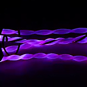
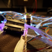
I have finally gotten the hardware in (mostly) working order for my wacky fiber optic light suit. Let's check out what I've done!
I'm using six of the same sensor in my fiber optic suit, with only four hardware configurable addresses. I need to take advantage of my ESP32 to create multiple I2C buses.
Terrify your coworkers! Annoy your friends! How many people in upper management can I frighten without losing my job?
I'm doing a whole lot of package development for Microsoft MakeCode; let's take a closer look at how it works.
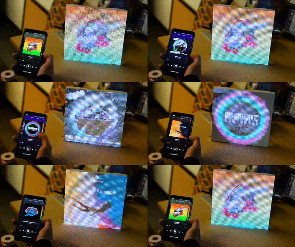
Wes and I collaborated on some code to take your current Spotify album art and display it on a 64x64 LED matrix. Let's check it out!
I recently figured out how to make a custom-shaped screen using an ESP32 and DMX512 over ArtNet. Let's check it out.
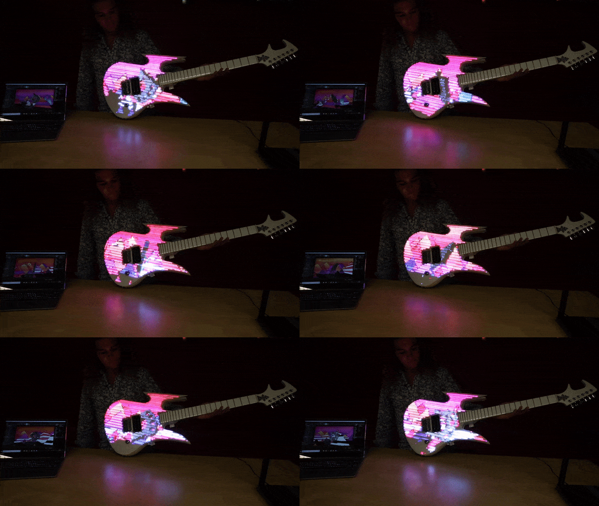
I was recently approached by music producer Decadon to add lights to an already custom guitar to make it even more one-of-a-kind. Let's check out some of the challenges I faced.
Let's figure out just how fast we can push data through APA102 pixels. Then let's look at what we can do with super fast lights.
ArtNet DMX is an industry standard in wireless lighting control. Let's figure out how to create our own ArtNet node so we can control pixels over the WiFi. We'll also figure out how to set up our custom fixture in Resolume Arena 6.
As Andrew finishes up his fiber optic light suit, he's adding in gesture control. Let's see how it works.
Andy is working on an audio control subsystem for his new fiber optic rave suit...let's check it out.
A look at the design considerations of rebuilding the fiber optic mounts for my light suit to accommodate new fiber optics and LEDs
Qwiic Distance Sensor (VL53L1X, VL53L4CD) Hookup Guide
February 10, 2022
The Qwiic Distance Sensor - VL53L1X is a time of flight sensor that is capable of several modes, as well as having a range of 4M. It's cousin VL53L4CD is also a time of flight sensor with similar characteristics but it has a range of about 1.3M. Let's hook it up and find out just how far away that thing over there is.
Triple Axis Accelerometer Breakout - KX13x (Qwiic) Hookup Guide
May 6, 2021
Get started measuring acceleration and vibration using the Triple Axis Accelerometer Breakout - KX134 (Qwiic) & KX132 (Qwiic) following this Hookup Guide.
SparkFun QwiicBus Hookup Guide
April 1, 2021
Build a long-range, noise-isolated I2C bus with the SparkFun QwiicBus Kit featuring the QwiicBus EndPoint and MidPoint following this Hookup Guide.
SparkFun PIR Breakout Hookup Guide
March 25, 2021
Get started with these Panasonic EKM-Series PIR breakouts following this Hookup Guide.
Qwiic PIR Hookup Guide
March 25, 2021
Get started passively monitoring motion using the Panasonic EKMC and EKMB sensors with the SparkFun Qwiic PIR.
SparkFun Qwiic GPIO Hookup Guide
October 8, 2020
Add up to 8 extra I/O pins to your microcontroller with the SparkFun Qwiic GPIO. Get started with the Qwiic GPIO in this Hookup Guide.
SparkFun Qwiic Dual Solid State Relay Hookup Guide
September 24, 2020
A Hookup Guide to get you started with the SparkFun Qwiic Dual Solid State Relay.
SparkFun Qwiic Quad Solid State Relay Kit Hookup Guide
July 16, 2020
A Hookup Guide to get you started with the SparkFun Qwiic Quad Solid State Relay Kit (say that five times fast!).
ESP32 OTA Updates over BLE from a React Web Application
July 2, 2020
Learn how to flash firmware Over-the-Air using a BLE React WebApp and ESP32
SparkFun Air Quality Sensor - SGP30 (Qwiic) Hookup Guide
June 5, 2020
A hookup guide to get started with the SparkFun Air Quality Sensor - SGP30 (Qwiic).
Real Time Clock Module - RV-8803 (Qwiic) Hookup Guide
April 2, 2020
A Hookup Guide for the SparkFun Real Time Clock Module - RV-8803 (Qwiic). Learn how to integrate the RV-8803 into your next time-keeping project.
RED-V Development Guide
November 27, 2019
This guide will help you get the RED-V RedBoard or Thing Plus up and running for the exhaust port. Depending on personal preference, there are a few environments to get started with the boards. All wings report in... we're going in full-throttle.
RED-V Thing Plus Hookup Guide
November 22, 2019
This guide will go over the hardware of the RED-V Thing Plus.
RED-V RedBoard Hookup Guide
November 22, 2019
This guide will go over the hardware of the RED-V RedBoard.
SparkFun gator:UV Hookup Guide
September 5, 2019
The gator:UV is an I2C based UV sensor. This tutorial will get you started using the gator:UV with the micro:bit platform.
SparkFun gator:RTC Hookup Guide
September 5, 2019
The gator:RTC is an I2C based, real-time clock (RTC) for keeping time while your micro:bit isn't powered. This tutorial will get you started using the gator:RTC with the micro:bit platform.
SparkFun gator:log Hookup Guide
September 5, 2019
The gator:log is a serial communication based data logger. This tutorial will get you started using the gator:log with the micro:bit platform.
SparkFun gator:soil Hookup Guide
June 13, 2019
The gator:soil is analog soil moisture sensor. This tutorial will get you started using the gator:soil with the micro:bit platform.
SparkFun gator:environment Hookup Guide
June 13, 2019
The gator:environment combines two I2C sensors for temperature, humidity, pressure, eCO2, and eTVOC values. This tutorial will get you started using the gator:environment with the micro:bit platform.
SparkFun gator:microphone Hookup Guide
June 13, 2019
The gator:microphone is an I2C sensor for detecting sound with an electret microphone. This tutorial will get you started using the gator:microphone with the micro:bit platform.
SparkFun gator:particle Hookup Guide
June 13, 2019
The gator:particle is an I2C heart-rate monitor and pulse oximeter that can be used as a particle sensor. This tutorial will get you started using the gator:particle with the micro:bit platform.
SAMD51 Thing Plus Hookup Guide
May 24, 2019
This tutorial covers the basic functionality of the SAMD51 Thing Plus and highlights the features of the new ARM Cortex-M4F development board.
Qwiic pHAT for Raspberry Pi Hookup Guide
May 23, 2019
Get started interfacing your Qwiic enabled boards with your Raspberry Pi. The Qwiic pHAT connects the I2C bus (GND, 3.3V, SDA, and SCL) on your Raspberry Pi to an array of Qwiic connectors.
How to Create a MakeCode Package for Micro:Bit
April 16, 2019
Learn how to develop code blocks for the Micro:bit in Microsoft MakeCode!
SparkFun ESP32 DMX to LED Shield
March 28, 2019
Learn how to utilize your DMX to LED Shield in a variety of different ways.
Qwiic Proximity Sensor (VCNL4040) Hookup Guide
February 28, 2019
The SparkFun Qwiic Proximity Sensor is a great, qualitative proximity (up to 20 cm) and light sensor. This hookup guide covers a few examples to retrieve basic sensor readings.
Qwiic Transparent OLED HUD Hookup Guide
February 21, 2019
Learn how to connect that sweet transparent OLED.
SparkFun gator:bit v2 Hookup Guide
January 31, 2019
The gator:bit v2 is a breakout board for the BBC micro:bit. The gator:bit exposes almost every pin on the micro:bit to clippable pad with circuit protection. It also has as built-in addressable LEDs and a built-in buzzer.
LuMini 8x8 Matrix Hookup Guide
January 24, 2019
The LuMini 8x8 Matrix (APA102-2020) are the highest resolution LED matrix available.
Live Spotify Album Art Display
January 23, 2019
Learn how to turn our 64x64 RGB LED Matrix Panel into a display for your current Spotify album art using an ESP32.
LuMini Ring Hookup Guide
January 17, 2019
The LuMini Rings (APA102-2020) are the highest resolution LED rings available.
Qwiic Single Relay Hookup Guide
January 3, 2019
Get started switching those higher power loads around with the Qwiic Single Relay.
Qwiic UV Sensor (VEML6075) Hookup Guide
December 20, 2018
Learn how to connect your VEML6075 UV Sensor and figure out just when you should put some sunscreen on.
SparkFun WiFi IR Blaster Hookup Guide
December 6, 2018
How to assemble the WiFi IR Blaster and program it using Arduino. You'll be controlling IR devices from the web in no time!
Introduction to DMX
November 14, 2018
DMX512 is an industry standard in lighting and stage design, whether it be controlling lights, motors, or lasers, DMX512 has many uses. In this tutorial we’ll cover DMX512 (Digital Multiplex with 512 pieces of information).
Gator:starter ProtoSnap Hookup Guide
October 18, 2018
Get started clipping sensors and lights to the micro:bit with the gator:starter gator:board from SparkFun!
Gator:color ProtoSnap Hookup Guide
October 18, 2018
Clip some LED's onto your gator:bit with the gator:color.
Gator:control ProtoSnap Hookup Guide
October 17, 2018
Buttons and switches and inputs oh my! Start adding more control to your gator:bit with the SparkFun gator:control.
Qwiic IR Array (MLX90640) Hookup Guide
September 20, 2018
The Melexis MLX90640 contains a 32x24 array of thermopile sensors creating, in essence, a low resolution thermal imaging camera. In this guide, we’ll go over how to connect your Qwiic Infrared Array with MLX90640 and get it communicating with Processing to produce a nice thermal image.
Qwiic Flex Glove Controller Hookup Guide
July 19, 2018
Is your finger bent? Is your finger straight? The Qwiic Flex Glove controller board will answer this age old question for you with the flex sensor!
Qwiic MUX Hookup Guide
July 19, 2018
Have a bunch of sensors with the same I2C address? Put them on the Qwiic MUX (TCA9548A) to get them all talking on the same bus!
RedBoard Edge Hookup Guide
June 1, 2018
The RedBoard Edge is a RedBoard that's been rebuilt around the idea that projects are eventually put into an enclosure to help clean up their look.
Qwiic Real Time Clock Module (RV-1805) Hookup Guide
May 31, 2018
Find out what time it is, even after the power's been out on your project for a while with the Qwiic Real Time Clock (RTC) module.
Flexible Grayscale OLED Hookup Guide
May 31, 2018
Figure out how to get images displaying on your new flexible OLED screen.
Qwiic Magnetometer (MLX90393) Hookup Guide
May 3, 2018
Figure out how magnetic fields are oriented, all without having to solder a thing.
Qwiic GRID-Eye Infrared Array (AMG88xx) Hookup Guide
May 3, 2018
The Panasonic GRID-Eye (AMG88xx) 8x8 thermopile array serves as a functional low-resolution infrared camera. This means you have a square array of 64 pixels each capable of independent temperature detection. It’s like having thermal camera (or Predator’s vision), just in really low resolution.
Qwiic VR IMU (BNO080) Hookup Guide
April 30, 2018
Figure out how things are oriented with the robust 9 degrees of freedom (DOF) BNO080 IMU. Maybe even make your own virtual reality (VR) applications if you're feeling savvy.
Qwiic Distance Sensor (RFD77402) Hookup Guide
April 5, 2018
The RFD77402 uses an infrared VCSEL (Vertical Cavity Surface Emitting Laser) TOF (Time of Flight) module capable of millimeter precision distance readings up to 2 meters. It’s also part of SparkFun’s Qwiic system, so you won’t have to do any soldering to figure out how far away things are.
Qwiic Accelerometer (MMA8452Q) Hookup Guide
April 5, 2018
Freescale’s MMA8452Q is a smart, low-power, three-axis, capacitive micro-machined accelerometer with 12-bits of resolution. It’s perfect for any project that needs to sense orientation or motion. We’ve taken that accelerometer and stuck it on a Qwiic-Enabled breakout board to make interfacing with the tiny, QFN package a bit easier.
Using Artnet DMX and the ESP32 to Drive Pixels
March 29, 2018
In this tutorial, we'll find out how to use Resolume Arena, a popular video jockey software, to control custom-made ArtNet DMX fixtures.
Qwiic Human Presence Sensor (AK9753) Hookup Guide
January 18, 2018
How to get started with your Qwiic enabled AK9753 Human Presence Sensor.
Qwiic Micro OLED Hookup Guide
January 18, 2018
Get started displaying things with the Qwiic Micro OLED.
Qwiic HAT for Raspberry Pi Hookup Guide
November 30, 2017
Get started interfacing your Qwiic enabled boards with your Raspberry Pi. This Qwiic connects the I2C bus (GND, 3.3V, SDA, and SCL) on your Raspberry Pi to an array of Qwiic connectors.
Qwiic Adapter Hookup Guide
November 30, 2017
Get started with your Qwiic adapter board. This adapter breaks out the I2C pins from the Qwiic connectors to pins that you can easily solder with your favorite I2C enabled device.
AS726X NIR/VIS Spectral Sensor Hookup Guide
October 19, 2017
It's now easier than ever to measure and characterize how different materials absorb and reflect different wavelengths of light. The AS726X spectral sensors allow you to detect wavelengths in the visible range (VIS) and near infrared range (NIR)!
SparkFun GPS Breakout - XA1110 (Qwiic) Hookup Guide
October 19, 2017
Figure out where in the world you are with the Qwiic SparkFun GPS Breakout - XA1110.
Qwiic Shield for Arduino & Photon Hookup Guide
October 19, 2017
Get started with our Qwiic ecosystem with the Qwiic shield for Arduino or Photon.
CCS811/BME280 (Qwiic) Environmental Combo Breakout Hookup Guide
September 8, 2017
Sense various environmental conditions such as temperature, humidity, barometric pressure, eCO2 and tVOCs with the CCS811 and BME280 combo breakout board.
-
I'd use this guy to tap into that 2x3 on the back, however please note that this isn't a JTAG connector, but the connector to program for the USB->JTAG interface IC. JTAG is only accessible over USB on this product. If you want to access JTAG lines on the FE310, you'll have to snag a Regular old RED-V
-
In it's current state, this board is not Arduino IDE compatible. The MK22FN128 Processor serves as a USB->JTAG interface (Pretty neat) to the FE310. Although it has a ridiculous amount of unused pins (It's an MCU doing a job well below it's pay-grade), this module is necessary as a USB->JTAG device to program the FE310.
-
All great points, this was my first ever design and I admittedly didn't really know what I was doing and have kind of been kicking myself ever since. I'll put together a revision now that it's been brought to my attention again. I think I could probably remove the Op amp altogether due to the internal PGA on the ADS1015. I'll also change that resistor divider to allow for a larger voltage swing
-
Hi Joel! To me, this sounds like an issue with clock stretching. The SHTC3 utilizes either clock stretching or it polls (pg.7) the SHTC3 while measurement is taking place. Particle Photon needs to have clock stretching specifically enabled in order for this sensor to be supported.
Does the sensor at least show up on an I2C bus scan?
-
Sure! Go ahead and click the text where I say "Few organization tools" and it'll download a zip of everything I've found moderately useful.
-
You should definitely completely solder header pins onto your Qwiic shield. If you don't have the pins soldered up, you probably won't make a good connection to the board.
-
The issue with having a 5th line be Interrupt or reset or something to that effect is that not all interrupts are the same, some are active high while most are active low. If there were a fifth line on Qwiic that were Interrupt, some sensors may try and pull it high, some may pull it low, leading to all sorts of issues. That's just the start, say we do have a fifth line and it's connected to interrupt, you receive an interrupt - but have no idea where it came from. Some sensors also have an interrupt input instead of an output, so one sensor firing an interrupt could trigger the interrupt input on another sensor when we wanted to trigger something on the microcontroller.
The solution to this problem is to have a dedicated GPIO to service the interrupt for each individual sensor so you know which sensor on the bus to ask for data when you receive an interrupt. If you had all of the interrupts bussed together, as you suggest, this option would not be possible as an interrupt from any one sensor would trigger an interrupt routine on all of the GPIO's connected to sensors (not good)
With a daisy-chainable system, sacrifices must be made.
-
It's this sweet low leakage diode which leaks only 100 nA at 50V.
The graph's look to be about 2 nA leakage at 3V
-
the 7-bit unshifted address is 0x32, however, the LSB determines whether a read or write occurs. Adding this LSB gives you 0x64 for a write and 0x65 for a read, but the base 7-bit address is still 0x32.
-
It is not, if we check out the schematic you can see that it is basically diode Or'ed with 3.3V into VDD on the RTC.
